Arduino Board Uno Rev3-Atmega 328: First Steps
Summary
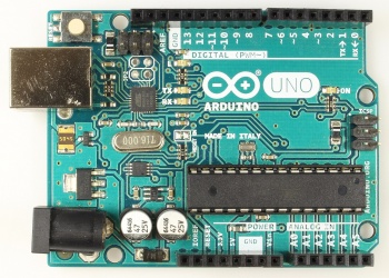
The Arduino UNO R3 is the current version of the Arduino UNO. This is the standard Arduino. It is completely sufficient for most projects and is very affordable.
Arduino UNO Overview
Main component is a microcontroller from ATMEL, the ATMEGA 328P. It contains the Arduino bootloader software. It allows to execute Arduino programs. The Arduino UNO has 14 digital I/O pins, six of which can be used as PWM channels (allow e.g. dimming of LEDs). Six analog input pins are also available. The board handles communication via UART, SPI and I2C (TWI).
For data exchange and programming it is connected to the computer via USB. Since the microcontroller cannot communicate directly via USB, there is a second microcontroller (ATmega8U2) on the Arduino UNO which does the "translation".
Structure of an Arduino UNO
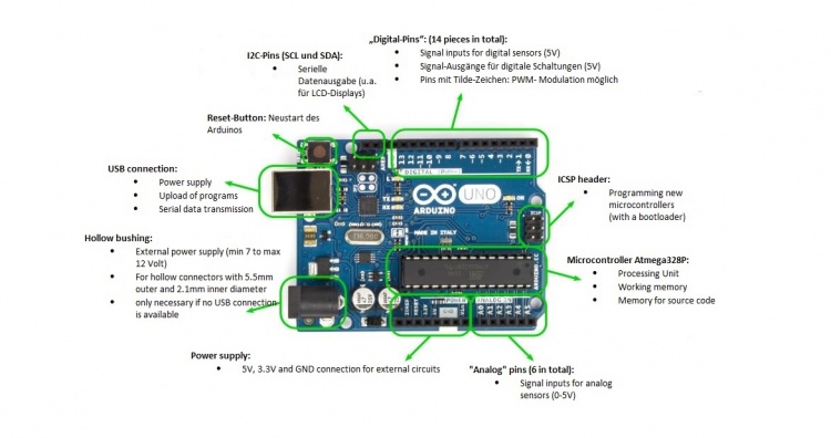
In the following figure the most important components of an Arduino UNO are listed with short descriptions.
The pin strips on both sides of the Arduino can be used to connect the Arduino to external electronic components or a circuit board using jumper cables:
➥ The analog pins A0 to A5 are suitable as sensor inputs for measuring voltage values between 0V and 5V; a built-in analog-to-digital converter
maps the measured voltage values to a numerical range from 0 (no voltage) to 1023 (maximum voltage, i.e. 5V).
➥ The digital pins 0 to 13 can also be defined as sensor inputs: An applied voltage of >2.5V is interpreted as HIGH (numerical value 1),
a lower voltage as LOW (numerical value 0).
➥ The digital pins 0 to 13 can also be defined as digital voltage outputs: They output a voltage of about 5V in HIGH mode and 0V in LOW mode.
However, the current is limited to 40mA; if necessary, the voltage of the pins is automatically reduced to reach this limit.
➥ A special feature is the digital pin 13: There the output current is limited to only 20mA, so that an LED can be connected there directly
(without series resistor) (directly next to pin 13 is a GND pin, so that not even a plug-in board is necessary for this).
Newer versions of the Arduino UNO even have an SMD LED permanently installed between pin 13 and GND.
➥ The pins (3, 5, 6, 9, 10, 11) marked with the tilde character ~ can, when set as output pins, also switch back and forth between 0V and 5V very
quickly by means of a so-called pulse width modulation (PWM).
You can specify values between 0 and 255, where 0 stands for "always off" and 255 for "always on".
➥ The other connectors on the board (AREF and ICSP headers) are not important for normal use.
Typical Arduino applications
➥ Electronics
➥ Robotics
➥ Controls
➥ Sensor data acquisition
➥ Programming close to the hardware
Used Hardware
➠ Arduino Board Uno Rev3 DIP Version, ATmega328, USB
➠ ARDUINO Wireless Proto Shield
➠ Arduino MKR LoRa Gateway Pro
References
➠ https://store.arduino.cc/arduino-uno-rev3

