Difference between revisions of "JTAGulator: Find IoT-Device's UART interface"
Jostrowski (talk | contribs) |
Jostrowski (talk | contribs) m (typo) |
||
| (4 intermediate revisions by the same user not shown) | |||
| Line 1: | Line 1: | ||
== Summary == | == Summary == | ||
Description | Description of how to find the UART interface of an IoT-Device. In this example the "smart" alarm system [[Technaxx WiFi smart alarm system starter kit TX-84]] will be used. | ||
== Requirements == | == Requirements == | ||
| Line 11: | Line 11: | ||
== UART explained == | == UART explained == | ||
UART stands for Universal Asynchronous Receiver/Transmitter and is a communication specification between | UART stands for Universal Asynchronous Receiver/Transmitter and is a serialized asynchronous communication specification between two devices. The communication can be simplex, half-duplex or duplex. | ||
; UART consist out of: | ; UART consist out of: | ||
| Line 19: | Line 19: | ||
* Gnd .. Ground 0V (optional) | * Gnd .. Ground 0V (optional) | ||
whereas the RX from | whereas the RX from one device is connected to the TX from the other device | ||
http://www.circuitbasics.com/wp-content/uploads/2016/01/Introduction-to-UART-Basic-Connection-Diagram-300x147.png | http://www.circuitbasics.com/wp-content/uploads/2016/01/Introduction-to-UART-Basic-Connection-Diagram-300x147.png | ||
| Line 29: | Line 29: | ||
http://www.circuitbasics.com/wp-content/uploads/2016/01/Introduction-to-UART-Packet-Frame-and-Bits-2.png | http://www.circuitbasics.com/wp-content/uploads/2016/01/Introduction-to-UART-Packet-Frame-and-Bits-2.png | ||
; UART packet | ; UART packet are defined as followed: | ||
: - Start Bit: A connected | : - Start Bit: A connected not-sending data-line is kept at the Vcc voltage (idle, but can also be the reverse). When one party wants to send data it indicates it by pulling the data-line to ground. | ||
: - Data Frame: The actual data | : - Data Frame: The actual data section allows to send 5 to 9 bits per packet. | ||
: - Parity: To detect transmission errors a checksum is appended to the packet. There are different modes: total of all even bits, total of all uneven bits | : - Parity: To detect transmission errors a checksum is appended to the packet. There are different modes: total of all even bits, total of all uneven bits. | ||
: - Stop Bit: To | : - Stop Bit: To end the packet the data-line is set to Vcc for 1 or 2 bit duration. | ||
* Data Frame can only | * The Data Frame can only send 9 bits when the Parity Bit is turned off. The Data Frame "borrows" the extra bit from the Parity Bit. | ||
* Data is send | * Data is send using least significant bit first. | ||
* The baud rate of the 2 devices should be within +-10% | |||
[[File:UART.png| | [[File:UART.png|400px|border]] | ||
Source and Images: | |||
* https://en.wikipedia.org/wiki/Universal_asynchronous_receiver-transmitter | * https://en.wikipedia.org/wiki/Universal_asynchronous_receiver-transmitter | ||
* http://www.circuitbasics.com/basics-uart-communication/ | * http://www.circuitbasics.com/basics-uart-communication/ | ||
| Line 46: | Line 47: | ||
== Find UART interface == | == Find UART interface == | ||
As explained in the section before the UART interface consists out of two pins: RX and TX. Usually also the pins Gnd and Vcc are laid out together. Therefore these 4 pins are usually right next to each other in a line. | |||
We look at this mainboard we can see 4 pins next to each other. | |||
If you can't find them it helps to look at the datasheet of the microprocessor. It is good practice to remove the UART interface of the device since this should only be accessible for testing. (exceptions exist) | |||
== Connect to the possible pins == | |||
Connect the JTAGulator Gnd Channel to the Gnd of the target device. Then connect the channels (start with 0 and proceed incrementally) to the possible pins of the UART. | |||
(Tip: you do not have to connect to the Gnd and Vcc of the target device since Gnd is already connected and Vcc has to be set in the software of the JTAGulator) | |||
== Connect to the JTAGualtor == | |||
''This tutorial is based on the firmware version 1.6'' | |||
Make sure you connected the target device to power. | |||
; Connect the JTAGulator to the computer | |||
: and open a serial connection using the following parameters: (eg. use Putty, minicom, ...) | |||
:: 115200 bps, 8 data bits, no parity, 1 stop bit | |||
; Go into the UART menu | |||
: Type <code>U</code> for the UART menu | |||
: Type <code>H</code> for help and all possible commands | |||
; Find UART pin configuration | |||
: Set the voltage level of the target device | |||
:: <code>V</code> and enter Vcc (if not known check with oscilloscope of multimeter) | |||
: Type <code>U</code> in the UART menu to start the brute force on the pin configuration of the UART pins. | |||
: Enter the text string you want to output on the UART interface: | |||
:: Usually you want to keep the <code>default configuration [CR]</code> so <code>just press enter</code> | |||
:: Usually when pressing <code>enter</code> into a UART interface it will great you with a response. | |||
: Enter starting channel of the JTAGulator | |||
: Enter ending channel of the JTAGulator | |||
:: Now the JTAGulator will cycle through all pin configurations and possible baud rates and prints out the output character you specified | |||
UART> u | |||
UART pin naming is from the target's perspective. | |||
Enter text string to output (prefix with \x for hex) [CR]: | |||
Enter starting channel [0]: | |||
Enter ending channel [4]: | |||
Possible permutations: 20 | |||
Ignore non-printable characters? [y/N]: n | |||
Press spacebar to begin (any other key to abort)... | |||
JTAGulating! Press any key to abort... | |||
---------- | |||
TXD: 2 | |||
RXD: 3 | |||
Baud: 19200 | |||
Data: ..(t0d^l.. ..... [ AF 85 28 74 30 64 5E 6C D9 0F 20 B7 E7 A5 F5 D4 ] | |||
TXD: 2 | |||
RXD: 3 | |||
Baud: 57600 | |||
Data: ...[32;40m00:16: [ 0D 0A 1B 5B 33 32 3B 34 30 6D 30 30 3A 31 36 3A ] | |||
TXD: 2 | |||
RXD: 3 | |||
Baud: 76800 | |||
Data: . [ 0C ] | |||
... | |||
TXD: 2 | |||
RXD: 4 | |||
Baud: 115200 | |||
Data: ................ [ 9E CF 0F 98 06 9E 0F 0F 98 98 E0 CF F3 98 E6 98 ] | |||
--------- | |||
UART scan complete. | |||
We can see that the JTAGulator received some input. Now you have to filter out the right combination by looking at the output. The UART interface will send back some ASCII characters. 0x0D / 0x0A are very good indicator signalling a carriage return / newline. So the second output (TX:2 RX:3 Baud:56700) looks very promising | |||
; Check the found UART pin configuration | |||
: Now we will use the UART pass-through to send terminal input directly through the JTAGulator to the specific UART pin configuration | |||
Restarting the target device (alarmsystem) gives us the perfect example to disable the UART as a debugging interface | |||
-Boot 1.1.3 (May 24 2016 - 11:52:40) | |||
Board: Dahua Tech Soc DRAM: 64 MB | |||
relocate_code Pointer at: 83fb8000 | |||
*********************** | |||
Watchdog Reset Occurred | |||
*********************** | |||
flash manufacture id: ef, device id 40 18 | |||
find flash: W25Q128BV | |||
env_relocate[232] malloced ENV at 83f78010 | |||
============================================ | |||
Ralink UBoot Version: 4.3.0.0 | |||
-------------------------------------------- | |||
ASIC 7628_MP (Port5<->None) | |||
DRAM component: 512 Mbits DDR, width 16 | |||
DRAM bus: 16 bit | |||
Total memory: 64 MBytes | |||
Flash component: SPI Flash | |||
Date:May 24 2016 Time:11:52:40 | |||
============================================ | |||
icache: sets:512, ways:4, linesz:32 ,total:65536 | |||
dcache: sets:256, ways:4, linesz:32 ,total:32768 | |||
##### The CPU freq = 580 MHZ #### | |||
estimate memory size =64 Mbytes | |||
RESET MT7628 PHY!!!!!! | |||
Please choose the operation: | |||
1: Load system code to SDRAM via TFTP. | |||
2: Load system code then write to Flash via TFTP. | |||
3: Boot system code via Flash (default). | |||
*: Entr boot command line interface. | |||
5: Load img then write to Flash via TFTP. | |||
7: Load Boot Loader code then write to Flash via Serial. | |||
9: Load Boot Loader code then write to Flash via TFTP. | |||
default: 3 | |||
0 | |||
3: System Boot system code via Flash. | |||
## Booting image at bc050000 ... | |||
Image Name: Linux Kernel Image | |||
Image Type: MIPS Linux Kernel Image (lzma compressed) | |||
Data Size: 2621376 Bytes = 2.5 MB | |||
Load Address: 80000000 | |||
Entry Point: 8000c150 | |||
Verifying Checksum ... OK | |||
Uncompressing Kernel Image ... OK | |||
No initrd | |||
## Transferring control to Linux (at address 8000c150) ... | |||
## Giving linux memsize in MB, 64 | |||
Starting kernel ... | |||
LINUX started... | |||
Linux version 2.6.36+ (wu_zhongren@centos128) (gcc version 4.6.3 (Buildroot 2012.11.1) ) #1 Wed Nov 30 19:48:01 CST 2016 | |||
The CPU feqenuce set to 580 MHz | |||
MIPS CPU sleep mode enabled. | |||
prom_envp(0)=memsize=64 ace in production: | |||
'''Ohh look it started Linux :)''' | |||
further down in the output we can see following: | |||
00:00:17|[NetApp-364975] debug tid:344 tid:344, P2P current config:[ | |||
{ | |||
"Address" : "www.easy4ipcloud.com", | |||
"Enable" : true, | |||
"Key" : "YXQ3Maxxxxxxxxx", | |||
"Port" : 8800, | |||
"RecvBufferSize" : 524288, | |||
"RegisterPort" : 12366, | |||
"RegisterServer" : "www.easy4ip.com", | |||
"ThreadNum" : 1, | |||
"Type" : "dhp2p", | |||
"UUID" : "3F0073EPAN00338", | |||
"WebVersion" : "2.211.0" | |||
} | |||
] | |||
''' Oh look it also printed out some password! ''' | |||
(I replaced the last characters of the password with x) | |||
Let's see what happens if I press enter: | |||
user name: | |||
password: | |||
23:50:23|[Manager] info tid:360 CLocalClient::CLocalClient(0x0x1c28f90)>>>>>> | |||
23:50:23|[libInfra] warn tid:360 [Src/Component/Client.cpp:67] this:0x1c28f90 tid:360, userName of client is a null string! | |||
23:50:23|[libInfra] warn tid:360 [Sr c/Component/Client.cpp:67] this:0x1c28f90 tid:360, userName of client is a null string! | |||
23:50:23|[Manager] info tid:360 si.l oginType=0, si.clientAddress=, si.clientType=Consol e si.authorityInfo= si.authorityType= si.passwordType=Plain | |||
23:50:23|[Manager] error tid:360 CLo calClient::login() fa iled with:268632070! | |||
23:50:23|[Manager] info tid:360 CLocalClient::~CLocalClie nt(0x0x1c28f90)>>>>>> | |||
User not valid! | |||
user name: | |||
'''Oh look it asks for a username and password''' | |||
Let's test admin:admin | |||
23:50:27|[Manager] debug tid:360 CLocalClient::login() successful! username = admin | |||
... well that was easy 😅 | |||
and the best part is: '''I am logged into root''' :) | |||
== Used Hardware == | == Used Hardware == | ||
[[JTAGulator]] | [[JTAGulator]] | ||
[[Technaxx WiFi smart alarm system starter kit TX-84]] | [[Technaxx WiFi smart alarm system starter kit TX-84]]] | ||
[[Category:Documentation]] | [[Category:Documentation]] | ||
Revision as of 10:02, 30 January 2020
Summary
Description of how to find the UART interface of an IoT-Device. In this example the "smart" alarm system Technaxx WiFi smart alarm system starter kit TX-84 will be used.
Requirements
- Read subsection 'Finding UART' of JTAGulator: Introduction to understand the basic commands available.
- JTAGualtor
- Technaxx WiFi smart alarm system starter kit TX-84 or some other device
UART explained
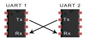
UART stands for Universal Asynchronous Receiver/Transmitter and is a serialized asynchronous communication specification between two devices. The communication can be simplex, half-duplex or duplex.
- UART consist out of
- TX .. Transmit
- RX .. Receive
- Vcc .. Supply Voltage (optional)
- Gnd .. Ground 0V (optional)
whereas the RX from one device is connected to the TX from the other device
The two devices should have the same ground and same Vcc
Data transmission
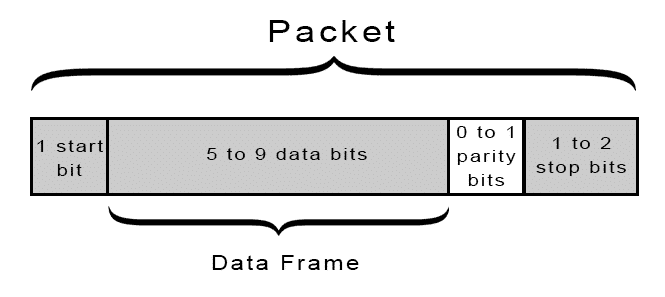
- UART packet are defined as followed
- - Start Bit: A connected not-sending data-line is kept at the Vcc voltage (idle, but can also be the reverse). When one party wants to send data it indicates it by pulling the data-line to ground.
- - Data Frame: The actual data section allows to send 5 to 9 bits per packet.
- - Parity: To detect transmission errors a checksum is appended to the packet. There are different modes: total of all even bits, total of all uneven bits.
- - Stop Bit: To end the packet the data-line is set to Vcc for 1 or 2 bit duration.
- The Data Frame can only send 9 bits when the Parity Bit is turned off. The Data Frame "borrows" the extra bit from the Parity Bit.
- Data is send using least significant bit first.
- The baud rate of the 2 devices should be within +-10%

Source and Images:
- https://en.wikipedia.org/wiki/Universal_asynchronous_receiver-transmitter
- http://www.circuitbasics.com/basics-uart-communication/
Find UART interface
As explained in the section before the UART interface consists out of two pins: RX and TX. Usually also the pins Gnd and Vcc are laid out together. Therefore these 4 pins are usually right next to each other in a line.
We look at this mainboard we can see 4 pins next to each other.
If you can't find them it helps to look at the datasheet of the microprocessor. It is good practice to remove the UART interface of the device since this should only be accessible for testing. (exceptions exist)
Connect to the possible pins
Connect the JTAGulator Gnd Channel to the Gnd of the target device. Then connect the channels (start with 0 and proceed incrementally) to the possible pins of the UART.
(Tip: you do not have to connect to the Gnd and Vcc of the target device since Gnd is already connected and Vcc has to be set in the software of the JTAGulator)
Connect to the JTAGualtor
This tutorial is based on the firmware version 1.6
Make sure you connected the target device to power.
- Connect the JTAGulator to the computer
- and open a serial connection using the following parameters: (eg. use Putty, minicom, ...)
- 115200 bps, 8 data bits, no parity, 1 stop bit
- Go into the UART menu
- Type
Ufor the UART menu - Type
Hfor help and all possible commands - Find UART pin configuration
- Set the voltage level of the target device
Vand enter Vcc (if not known check with oscilloscope of multimeter)
- Type
Uin the UART menu to start the brute force on the pin configuration of the UART pins. - Enter the text string you want to output on the UART interface:
- Usually you want to keep the
default configuration [CR]sojust press enter - Usually when pressing
enterinto a UART interface it will great you with a response.
- Usually you want to keep the
- Enter starting channel of the JTAGulator
- Enter ending channel of the JTAGulator
- Now the JTAGulator will cycle through all pin configurations and possible baud rates and prints out the output character you specified
UART> u
UART pin naming is from the target's perspective.
Enter text string to output (prefix with \x for hex) [CR]:
Enter starting channel [0]:
Enter ending channel [4]:
Possible permutations: 20

Ignore non-printable characters? [y/N]: n
Press spacebar to begin (any other key to abort)...
JTAGulating! Press any key to abort...
----------
TXD: 2
RXD: 3
Baud: 19200
Data: ..(t0d^l.. ..... [ AF 85 28 74 30 64 5E 6C D9 0F 20 B7 E7 A5 F5 D4 ]

TXD: 2
RXD: 3
Baud: 57600
Data: ...[32;40m00:16: [ 0D 0A 1B 5B 33 32 3B 34 30 6D 30 30 3A 31 36 3A ]

TXD: 2
RXD: 3
Baud: 76800
Data: . [ 0C ]

...

TXD: 2
RXD: 4
Baud: 115200
Data: ................ [ 9E CF 0F 98 06 9E 0F 0F 98 98 E0 CF F3 98 E6 98 ]
---------
UART scan complete.
We can see that the JTAGulator received some input. Now you have to filter out the right combination by looking at the output. The UART interface will send back some ASCII characters. 0x0D / 0x0A are very good indicator signalling a carriage return / newline. So the second output (TX:2 RX:3 Baud:56700) looks very promising
- Check the found UART pin configuration
- Now we will use the UART pass-through to send terminal input directly through the JTAGulator to the specific UART pin configuration
Restarting the target device (alarmsystem) gives us the perfect example to disable the UART as a debugging interface
-Boot 1.1.3 (May 24 2016 - 11:52:40)

Board: Dahua Tech Soc DRAM:  64 MB
relocate_code Pointer at: 83fb8000
***********************
Watchdog Reset Occurred
***********************
flash manufacture id: ef, device id 40 18
find flash: W25Q128BV
env_relocate[232] malloced ENV at 83f78010
============================================
Ralink UBoot Version: 4.3.0.0
--------------------------------------------
ASIC 7628_MP (Port5<->None)
DRAM component: 512 Mbits DDR, width 16
DRAM bus: 16 bit
Total memory: 64 MBytes
Flash component: SPI Flash
Date:May 24 2016  Time:11:52:40
============================================
icache: sets:512, ways:4, linesz:32 ,total:65536
dcache: sets:256, ways:4, linesz:32 ,total:32768

 ##### The CPU freq = 580 MHZ ####
 estimate memory size =64 Mbytes
RESET MT7628 PHY!!!!!!

Please choose the operation:
   1: Load system code to SDRAM via TFTP.
   2: Load system code then write to Flash via TFTP.
   3: Boot system code via Flash (default).
   *: Entr boot command line interface.
   5: Load img then write to Flash via TFTP.
   7: Load Boot Loader code then write to Flash via Serial.
   9: Load Boot Loader code then write to Flash via TFTP.
default: 3
 0

3: System Boot system code via Flash.
## Booting image at bc050000 ...
   Image Name:   Linux Kernel Image
   Image Type:   MIPS Linux Kernel Image (lzma compressed)
   Data Size:    2621376 Bytes =  2.5 MB
   Load Address: 80000000
   Entry Point:  8000c150
   Verifying Checksum ... OK
   Uncompressing Kernel Image ... OK
No initrd
## Transferring control to Linux (at address 8000c150) ...
## Giving linux memsize in MB, 64

Starting kernel ...


LINUX started...
Linux version 2.6.36+ (wu_zhongren@centos128) (gcc version 4.6.3 (Buildroot 2012.11.1) )  #1 Wed Nov 30 19:48:01 CST 2016

 The CPU feqenuce set to 580 MHz

 MIPS CPU sleep mode enabled.
prom_envp(0)=memsize=64  ace in production:
Ohh look it started Linux :)
further down in the output we can see following:
00:00:17|[NetApp-364975] debug tid:344 tid:344, P2P current config:[
   {
      "Address" : "www.easy4ipcloud.com",
      "Enable" : true,
      "Key" : "YXQ3Maxxxxxxxxx",
      "Port" : 8800,
      "RecvBufferSize" : 524288,
      "RegisterPort" : 12366,
      "RegisterServer" : "www.easy4ip.com",
      "ThreadNum" : 1,
      "Type" : "dhp2p",
      "UUID" : "3F0073EPAN00338",
      "WebVersion" : "2.211.0"
   }
]
Oh look it also printed out some password!
(I replaced the last characters of the password with x)
Let's see what happens if I press enter:
user name:
password:
23:50:23|[Manager] info tid:360 CLocalClient::CLocalClient(0x0x1c28f90)>>>>>>
23:50:23|[libInfra] warn tid:360 [Src/Component/Client.cpp:67] this:0x1c28f90 tid:360,  userName of client is a null string!
23:50:23|[libInfra] warn tid:360 [Sr c/Component/Client.cpp:67] this:0x1c28f90 tid:360,  userName of client is a null string!
23:50:23|[Manager] info tid:360 si.l oginType=0, si.clientAddress=, si.clientType=Consol e  si.authorityInfo= si.authorityType=  si.passwordType=Plain
23:50:23|[Manager] error tid:360 CLo calClient::login() fa iled with:268632070!
23:50:23|[Manager] info tid:360 CLocalClient::~CLocalClie nt(0x0x1c28f90)>>>>>>
User not valid!
user name:
Oh look it asks for a username and password
Let's test admin:admin
23:50:27|[Manager] debug tid:360 CLocalClient::login() successful! username = admin
... well that was easy 😅
and the best part is: I am logged into root :)
Used Hardware
JTAGulator Technaxx WiFi smart alarm system starter kit TX-84]