JTAGulator: Find IoT-Device's UART interface
Revision as of 12:48, 2 December 2019 by Jostrowski (talk | contribs)
Summary
Description on how to find the UART interface of an IoT-Device. In this example the "smart" alarm system Technaxx WiFi smart alarm system starter kit TX-84 will be used.
Requirements
- Read subsection 'Finding UART' of JTAGulator: Introduction to understand the basic commands available.
- JTAGualtor
- Technaxx WiFi smart alarm system starter kit TX-84 or some other device
UART explained
UART stands for Universal Asynchronous Receiver/Transmitter and is a communication specification between to devices and allows for a serialized asynchronous communication.
- UART consist out of
- TX .. Transmit
- RX .. Receive
- Vcc .. Supply Voltage (optional)
- Gnd .. Ground 0V (optional)
whereas the RX from on device is connected to the TX from the other device
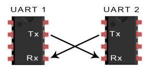
The two devices should have the same ground and same Vcc
Data transmission
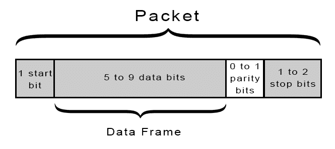
- UART packet is defined as followed
- - Start Bit: A connected non sending data-line is kept at the Vcc voltage (idle, but can also be reversed). When one party wants to send data it indicates it by pulling the data-line to ground.
- - Data Frame: The actual data consisting of 5 to 9 bits is sent over the line.
- - Parity: To detect transmission errors a checksum is appended to the packet. There are different modes: total of all even bits, total of all uneven bits, or non.
- - Stop Bit: To signal the end of a connection the data-line is pulled to high for a 1 or 2 bit duration.
- Data Frame can only have 9 bits, when the parity bit is turned off. Otherwise is can have up to 8 bits.
- Data is send Least Significant Bit (LSB) first.

Sources:
- https://en.wikipedia.org/wiki/Universal_asynchronous_receiver-transmitter
- http://www.circuitbasics.com/basics-uart-communication/
Find UART interface
Used Hardware
JTAGulator Technaxx WiFi smart alarm system starter kit TX-84