Difference between revisions of "JTAGulator: Introduction"
Jump to navigation
Jump to search
Jostrowski (talk | contribs) (Created page with "== Summary == The JTAGulator is tool to assist identifying JTAG and USART pins. JTAG (named after the Joint Test Action Group) is an industry standard for verifying designs...") |
Jostrowski (talk | contribs) |
||
| Line 2: | Line 2: | ||
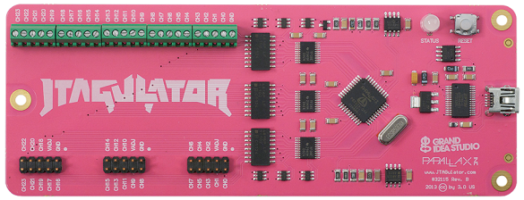
The JTAGulator is tool to assist identifying JTAG and USART pins. | The JTAGulator is tool to assist identifying JTAG and USART pins. | ||
[[File:JTAGulator.png|right]] | |||
JTAG (named after the Joint Test Action Group) is an industry standard for verifying designs and testing printed circuit boards after manufacture. | JTAG (named after the Joint Test Action Group) is an industry standard for verifying designs and testing printed circuit boards after manufacture. | ||
JTAG allows for many applications: | ; JTAG allows for many applications: | ||
* Debugging of hardware | :* Debugging of hardware | ||
* Debugging of software | :* Debugging of software | ||
* Program / Modify internal memory | :* Program / Modify internal memory | ||
JTAG consist of 4 essential signals: | ; JTAG consist of 4 essential signals: | ||
* '''TCK''' ... Test Clock | :* '''TCK''' ... Test Clock | ||
* '''TMS''' ... Test Mode Select (Steuerung) | :* '''TMS''' ... Test Mode Select (Steuerung) | ||
* '''TDI''' ... Test Data In | :* '''TDI''' ... Test Data In | ||
* '''TDO''' ... Test Data Out | :* '''TDO''' ... Test Data Out | ||
additional signals: | ; additional signals: | ||
* ''' | :* '''Vcc''' ... 3.3V | ||
* ''' | :* '''GND''' ... ground | ||
* '''TRST''' .. test reset (low active) | :* '''TRST''' .. test reset (low active) | ||
:* '''RST''' ... system reset (low active) | |||
Manufactures have '''different''' Pin Layout, for Cortex Connectors it looks like this: | |||
[[File:JTAG connections.png|source:http://www.keil.com/support/man/docs/ulink2/ulink2_connector_20_16_14_10pin.png|500px]] | |||
== JTAGulator Overview == | |||
Since JTAG pins are not always labelled, they can be hard to find. This is when the JTAGulator comes into play. | |||
You connect the channels of the JTAGulator to different test pins on the hardware you want to analyze. | |||
The JTAGulator test each individual pins and tries to find JTAG connections. If found it will output the correct JTAG pins. | |||
== Usage == | |||
; Connect the JTAGulator via serial to the computer | |||
: 115200 bps, 8 data bits, no parity, 1 stop bit | |||
:* Linux: you can use minicom | |||
:* Windows: you can use Putty | |||
: You should see following output: | |||
INSERT IMAGE | |||
; Connect the JTAGulator to the test-device | |||
# Connect the JTAGulator '''Ground (GND)''' to the GND of the hardware you want to analyze. | |||
# Connect '''CHx''' from the JTAGulator to some pins on the hardware which may be JTAG pins (start from CH0). Do '''not''' use the '''VADJ''' pin on the JTAGualtor (VADJ is the output from the PWM/op amp hardware on the JTAGulator that's used to create the target system voltage and drive the on-board level translators.) | |||
# | |||
== Used Hardware == | == Used Hardware == | ||
[[ | [[JTAGulator]] | ||
== References == | == References == | ||
[[Category:Documentation]] | [[Category:Documentation]] | ||
Revision as of 14:39, 15 November 2019
Summary
The JTAGulator is tool to assist identifying JTAG and USART pins.

JTAG (named after the Joint Test Action Group) is an industry standard for verifying designs and testing printed circuit boards after manufacture.
- JTAG allows for many applications
-
- Debugging of hardware
- Debugging of software
- Program / Modify internal memory
- JTAG consist of 4 essential signals
-
- TCK ... Test Clock
- TMS ... Test Mode Select (Steuerung)
- TDI ... Test Data In
- TDO ... Test Data Out
- additional signals
-
- Vcc ... 3.3V
- GND ... ground
- TRST .. test reset (low active)
- RST ... system reset (low active)
Manufactures have different Pin Layout, for Cortex Connectors it looks like this:

JTAGulator Overview
Since JTAG pins are not always labelled, they can be hard to find. This is when the JTAGulator comes into play.
You connect the channels of the JTAGulator to different test pins on the hardware you want to analyze.
The JTAGulator test each individual pins and tries to find JTAG connections. If found it will output the correct JTAG pins.
Usage
- Connect the JTAGulator via serial to the computer
- 115200 bps, 8 data bits, no parity, 1 stop bit
- Linux: you can use minicom
- Windows: you can use Putty
- You should see following output:
INSERT IMAGE
- Connect the JTAGulator to the test-device
- Connect the JTAGulator Ground (GND) to the GND of the hardware you want to analyze.
- Connect CHx from the JTAGulator to some pins on the hardware which may be JTAG pins (start from CH0). Do not use the VADJ pin on the JTAGualtor (VADJ is the output from the PWM/op amp hardware on the JTAGulator that's used to create the target system voltage and drive the on-board level translators.)