Difference between revisions of "JTAGulator: Introduction"
Jostrowski (talk | contribs) |
Jostrowski (talk | contribs) m (typo) |
||
| Line 1: | Line 1: | ||
== JTAG explained == | == JTAG explained == | ||
The JTAGulator is tool to assist identifying JTAG and USART pins. | The JTAGulator is a tool to assist in identifying JTAG and USART pins. | ||
[[File:JTAGulator.png|right]] | [[File:JTAGulator.png|right]] | ||
JTAG (named after the Joint Test Action Group) is an industry standard for verifying designs and testing printed circuit boards after manufacture. | JTAG (named after the Joint Test Action Group) is an industry-standard for verifying designs and testing printed circuit boards after manufacture. | ||
; JTAG allows for many applications: | ; JTAG allows for many applications: | ||
:* Boundary Scan (read and set values of pin) | :* Boundary Scan (read and set values of a pin) | ||
:* Debugging of hardware / software | :* Debugging of hardware/software | ||
:* Program / Modify memory | :* Program / Modify memory | ||
:* Chips can be daisy chained, so you can access multiple chips through one interface | :* Chips can be daisy-chained, so you can access multiple chips through one interface | ||
; JTAG consist of 4 essential signals: | ; JTAG consist of 4 essential signals: | ||
| Line 27: | Line 27: | ||
Good video about the JTAG interface: [https://www.youtube.com/watch?v=TlWlLeC5BUs EEVblog #499 - What is JTAG and Boundary Scan?] | Good video about the JTAG interface: [https://www.youtube.com/watch?v=TlWlLeC5BUs EEVblog #499 - What is JTAG and Boundary Scan?] | ||
Manufactures have '''different''' Pin Layout, for Cortex Connectors it looks like this: | Manufactures have '''different''' Pin Layout, for Cortex Connectors, it looks like this: | ||
[[File:JTAG connections.png|source:http://www.keil.com/support/man/docs/ulink2/ulink2_connector_20_16_14_10pin.png|500px]] | [[File:JTAG connections.png|source:http://www.keil.com/support/man/docs/ulink2/ulink2_connector_20_16_14_10pin.png|500px]] | ||
| Line 33: | Line 33: | ||
== JTAGulator Overview == | == JTAGulator Overview == | ||
Since JTAG pins are not always | Since JTAG pins are not always labeled, they can be hard to find. This is when the JTAGulator comes into play. | ||
You connect the channels of the JTAGulator to different test pins on the hardware you want to analyze. | You connect the channels of the JTAGulator to different test pins on the hardware you want to analyze. | ||
| Line 47: | Line 47: | ||
:* Linux: you can use minicom | :* Linux: you can use minicom | ||
:* Windows: you can use Putty | :* Windows: you can use Putty | ||
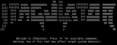
: You should see following output: | : You should see the following output: | ||
: [[File:JTAGulator welcomeScreen.png|400px]] | : [[File:JTAGulator welcomeScreen.png|400px]] | ||
; Connect the JTAGulator to the test-device | ; Connect the JTAGulator to the test-device | ||
# Connect the JTAGulator '''Ground (GND)''' to the GND of the hardware you want to analyze. | # Connect the JTAGulator '''Ground (GND)''' to the GND of the hardware you want to analyze. | ||
# Connect '''CHx''' from the JTAGulator to some pins '''(make sure via multimeter that the pins do not have a voltage | # Connect '''CHx''' from the JTAGulator to some pins '''(make sure via multimeter that the pins do not have a voltage level over 3.3V)''' on the hardware which may be JTAG pins (start from CH0). Do '''not''' use the '''VADJ''' pin on the JTAGualtor (VADJ is the output from the PWM/up-amp hardware on the JTAGulator that's used to create the target system voltage and drive the on-board level translators.) | ||
== JTAGulator commands == | == JTAGulator commands == | ||
| Line 75: | Line 75: | ||
: Enter x for the unknown TDI line and the numbers of the possible JTAG combination | : Enter x for the unknown TDI line and the numbers of the possible JTAG combination | ||
; Test BYPASS <code>T</code> | ; Test BYPASS <code>T</code> | ||
: After the TDI pin was found, test the communication using the echo command of the JTAG interface. | : After the TDI pin was found, test the communication using the echo command of the JTAG interface. A random string gets sent to the TDI line of the JTAG interface and the JTAG controller should now send the same string back on the TDO line. | ||
: With this you can make sure, that is really is a JTAG interface | : With this you can make sure, that is really is a JTAG interface | ||
: Go into the Test BYPASS menu, enter the number of the pins and see if the string matches | : Go into the Test BYPASS menu, enter the number of the pins and see if the string matches | ||
: If it does match it is very likely to be a JTAG interface, if not you will have to try out other pins. | : If it does match it is very likely to be a JTAG interface, if not you will have to try out other pins. | ||
'''For a real world example look into the post: [[JTAGulator: Find a Smartphone's JTAG interface]]''' | '''For a real-world example look into the post: [[JTAGulator: Find a Smartphone's JTAG interface]]''' | ||
---- | ---- | ||
| Line 86: | Line 86: | ||
=== Finding UART === | === Finding UART === | ||
The JTAGulator can also find UART pins by | The JTAGulator can also find UART pins by brute-forcing the pinout configuration as well as the baud-rate | ||
; Find UART pins | ; Find UART pins | ||
| Line 92: | Line 92: | ||
: (You can get help via <code>H</code>) | : (You can get help via <code>H</code>) | ||
* Set the voltage level with <code>V</code> | * Set the voltage level with <code>V</code> | ||
* Enter the | * Enter the brute-force mode: <code>U</code> | ||
* Set parameters (make sure you do not ignore non-printable characters) | * Set parameters (make sure you do not ignore non-printable characters) | ||
; Analyze output | ; Analyze output | ||
: If | : If the JTAGulator received a message it will output it to the screen | ||
* The JTAGulator will display the TX and RX pin, the | * The JTAGulator will display the TX and RX pin, the baud rate it was using and the message it received | ||
: In the default configuration the JTAGualtor will send <CR> (0x0D) commands to the device | : In the default configuration the JTAGualtor will send <CR> (0x0D) commands to the device | ||
: Usually UART interfaces answer on <CR> commands with a response and append a <LF> (0x0A) or <CR> ( 0x0D) to it. | : Usually UART interfaces answer on <CR> commands with a response and append a <LF> (0x0A) or <CR> ( 0x0D) to it. Receiving such bytes are a good indicator that the correct baud rate was used. | ||
; Connect to UART | ; Connect to UART | ||
: The JTAGualtor allows for passthrough of UART commands | : The JTAGualtor allows for passthrough of UART commands | ||
* Enter <code>P</code> for UART passthrough | * Enter <code>P</code> for UART passthrough | ||
: Set the RX, TX and the | : Set the RX, TX and the baud rate you found before. | ||
'''For an example visit: [[JTAGulator: Find IoT-Device's UART interface]]''' | '''For an example visit: [[JTAGulator: Find IoT-Device's UART interface]]''' | ||
Revision as of 10:06, 30 January 2020
JTAG explained
The JTAGulator is a tool to assist in identifying JTAG and USART pins.

JTAG (named after the Joint Test Action Group) is an industry-standard for verifying designs and testing printed circuit boards after manufacture.
- JTAG allows for many applications
-
- Boundary Scan (read and set values of a pin)
- Debugging of hardware/software
- Program / Modify memory
- Chips can be daisy-chained, so you can access multiple chips through one interface
- JTAG consist of 4 essential signals
-
- TCK ... Test Clock
- TMS ... Test Mode Select (Steuerung)
- TDI ... Test Data In
- TDO ... Test Data Out
- additional signals
-
- Vcc ... 3.3V
- GND ... ground
- TRST .. test reset (low active)
- RST ... system reset (low active)
Good video about the JTAG interface: EEVblog #499 - What is JTAG and Boundary Scan?
Manufactures have different Pin Layout, for Cortex Connectors, it looks like this:

JTAGulator Overview
Since JTAG pins are not always labeled, they can be hard to find. This is when the JTAGulator comes into play.
You connect the channels of the JTAGulator to different test pins on the hardware you want to analyze.
The JTAGulator test each individual pins and tries to find JTAG connections. If found it will output the correct JTAG pins.
Setup
- Make sure you have the latest firmware
- JTAGulator: Update firmware
- Connect the JTAGulator via serial to the computer
- 115200 bps, 8 data bits, no parity, 1 stop bit
- Linux: you can use minicom
- Windows: you can use Putty
- You should see the following output:

- Connect the JTAGulator to the test-device
- Connect the JTAGulator Ground (GND) to the GND of the hardware you want to analyze.
- Connect CHx from the JTAGulator to some pins (make sure via multimeter that the pins do not have a voltage level over 3.3V) on the hardware which may be JTAG pins (start from CH0). Do not use the VADJ pin on the JTAGualtor (VADJ is the output from the PWM/up-amp hardware on the JTAGulator that's used to create the target system voltage and drive the on-board level translators.)
JTAGulator commands
This tutorial is based on the firmware version 1.6
- Display all commands:
H - Display firmware version:
I
- First you need to set the voltage level
- Press
Vand set the voltage level accordingly (check via multimeter or hardware specification, usually 3.3)
Finding JTAG
- Type
Jto get to the JTAG commands - Then type
Hfor useful help-information
- IDCODE scan
I - This is a quick scan, which checks the output of every possible combination and presents possible combination + device IDs
- You can filter out incorrect JTAG identification by looking at the ID (device IDs are eye-catching, they are very non-uniform eg. (0x0D780237) and not like (0xFFFFFF7F) or (0x55555555) )
- BYPASS scan
B - After you used the IDcode scan, you want to determine the TDI line
- Enter x for the unknown TDI line and the numbers of the possible JTAG combination
- Test BYPASS
T - After the TDI pin was found, test the communication using the echo command of the JTAG interface. A random string gets sent to the TDI line of the JTAG interface and the JTAG controller should now send the same string back on the TDO line.
- With this you can make sure, that is really is a JTAG interface
- Go into the Test BYPASS menu, enter the number of the pins and see if the string matches
- If it does match it is very likely to be a JTAG interface, if not you will have to try out other pins.
For a real-world example look into the post: JTAGulator: Find a Smartphone's JTAG interface
Finding UART
The JTAGulator can also find UART pins by brute-forcing the pinout configuration as well as the baud-rate
- Find UART pins
- To enter the UART commands enter:
U
- (You can get help via
H)
- Set the voltage level with
V - Enter the brute-force mode:
U - Set parameters (make sure you do not ignore non-printable characters)
- Analyze output
- If the JTAGulator received a message it will output it to the screen
- The JTAGulator will display the TX and RX pin, the baud rate it was using and the message it received
- In the default configuration the JTAGualtor will send <CR> (0x0D) commands to the device
- Usually UART interfaces answer on <CR> commands with a response and append a <LF> (0x0A) or <CR> ( 0x0D) to it. Receiving such bytes are a good indicator that the correct baud rate was used.
- Connect to UART
- The JTAGualtor allows for passthrough of UART commands
- Enter
Pfor UART passthrough
- Set the RX, TX and the baud rate you found before.
For an example visit: JTAGulator: Find IoT-Device's UART interface