Keyestudio 4WD Bluetooth multifunctional car kit
Summary
This documentation is about how to program the Car and some tipps about the assembly.
Requirements
- Arduino IDE
- 18650 Batteries
Description
Component list
| Product Name | Quantity |
|---|---|
| keyestudio UNO R3 | 1 |
| keyestudio Shield V5 | 1 |
| keyestudio L298N Motor Shield | 1 |
| keyestudio Bluetooh HC-06 | 1 |
| I2C 1602 LCD | 1 |
| keyestudio Line Tracking Sensor | 3 |
| HC-SR04 Ultrasonic Sensor | 1 |
| keyestudio Digital IR Receiver Module | 1 |
| 4WD Top PCB | 1 |
| 4WD Bottom PCB | 1 |
| Servo Motor | 1 |
| Servo Plastic Platform | 1 |
| Remote Control of Chip | 1 |
| Toggle Switch + Wire | 1 |
| 18650 Battery Holder | 1 |
| Mental Motor | 4 |
| Motor Fixed Part | 4 |
| Plastic Tire | 4 |
| Copper Pillar 40MM | 6 |
| Copper Pillar 10MM | 16 |
| USB Cable | 1 |
| Jumper Wire | 30 |
| M3*6MM Round Head Screw | 60 |
| M3*8MM Flat Head Screw | 2 |
| M3*30MM Round Head Screw | 8 |
| 3MM Nut | 16 |
| Connector Wire (150mm, Black) | 6 |
| Connector Wire (150mm, Red) | 6 |
| Winding Wire (12CM) | 1 |
Assembly
Follow the User Manual. If something is unclear then watch a assembly video. Be careful when installing the motors, make sure they’re all properly aligned, if not the car will pull to one side. Especially take care that no cables sticks into the motors.
Motor control
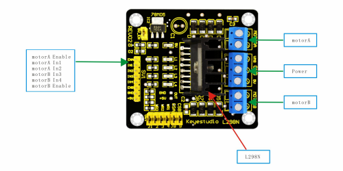
We control the motor using a H-Bridge L298N Motor Driver.
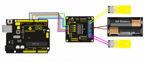
In our case we need to plug two motors to each motorA and motorB. Connect the power from the battery pack VSS and GND.
Wire the motor to the Arduino/Sensor Shield as adviced in the user manual.
Rotate Clockwise
//define the output pins.
int IN1=5;
int IN2=6;
int IN3=7;
int IN4=8;
int ENA=9;
int ENB=10;
void setup() {
  //set up the pins to act as output.
  for (int i = 5; i < 11;i++)
  {
    pinMode(i,OUTPUT);
  }
  delay(5000);
}
void loop() {
 //control the motor
 digitalWrite(IN1,LOW);
 digitalWrite(IN2,HIGH);
 digitalWrite(IN3,LOW);
 digitalWrite(IN4,HIGH);
 analogWrite(ENA,200);
 analogWrite(ENB,200);
 delay(1000);
 analogWrite(ENA,0);
 analogWrite(ENB,0);
 delay(1000);
}
Rotate Counter Clockwise
//define the output pins.
int IN1=5;
int IN2=6;
int IN3=7;
int IN4=8;
int ENA=9;
int ENB=10;

void setup() {
  //set up the pins to act as output.
  for (int i = 5; i < 11;i++)
  {
    pinMode(i,OUTPUT);
  }
  delay(5000);
}

void loop() {
 //control the motor
 digitalWrite(IN1,HIGH);
 digitalWrite(IN2,LOW);
 digitalWrite(IN3,HIGH);
 digitalWrite(IN4,LOW);
 analogWrite(ENA,200);
 analogWrite(ENB,200);
 delay(1000);
 analogWrite(ENA,0);
 analogWrite(ENB,0);
 delay(1000);
}
Drive Forward
void driveForward()
{
 analogWrite(ENA,0);
 analogWrite(ENB,0);
 digitalWrite(IN1,LOW);
 digitalWrite(IN2,HIGH);

 digitalWrite(IN3,HIGH);
 digitalWrite(IN4,LOW);
 delay(150);
 analogWrite(ENA,100);
 analogWrite(ENB,100);
}
Drive Reverse
void driveReverse()
{
 analogWrite(ENA,0);
 analogWrite(ENB,0);
 digitalWrite(IN1,HIGH);
 digitalWrite(IN2,LOW);

 digitalWrite(IN3,LOW);
 digitalWrite(IN4,HIGH);
 delay(150);
 analogWrite(ENA,100);
 analogWrite(ENB,100);
}
I2C Display
The display is controlled with I2C. I am using the Wire and LiquidCrystal_I2C library to control the display.
#include <Wire.h>
#include <LiquidCrystal_I2C.h>
//set the LCD address to 0x27 for a 16 chars and 2 line display
LiquidCrystal_I2C lcd(0x27,16,2);
void setup()
{
 //initialize the lcd
 lcd.init();
 //enable the backlight
 lcd.backlight();
 //set the cursor to the first line.
 lcd.setCursor(3,0);
 //print text
 lcd.print("Hello");
 //set the cursor in the next line.
 lcd.setCursor(3,1);
 //print text
 lcd.print("world!");
}

void loop()
{}
Servo Motor
The Servo Motor is controlled with PWM. The Sketch rotates the motor in an angle between 110 and 180 degres.
int servopin=2;// select digital pin 9 for servomotor signal line
int myangle;// initialize angle variable
int pulsewidth;// initialize width variable
int val;

void servopulse(int servopin,int myangle)// define a servo pulse function
{
  pulsewidth=(myangle*11)+500;// convert angle to 500-2480 pulse width
  digitalWrite(servopin,HIGH);// set the level of servo pin as “high”
  delayMicroseconds(pulsewidth);// delay microsecond of pulse width
  digitalWrite(servopin,LOW);// set the level of servo pin as “low”
  delay(20-pulsewidth/1000);
}

void setup()
{
  pinMode(servopin,OUTPUT);// set servo pin as “output”
  Serial.begin(9600);// connect to serial port, set baud rate at “9600”
  Serial.println("ready" ) ;
}

void loop(){
  val = 180;
  Serial.print("moving servo to ");
  Serial.print(val);
  Serial.println();
  for(int i=0;i<=25;i++) // giving the servo time to rotate to commanded position
  {
    servopulse(servopin,val);// use the pulse function
  }
  val = 110;
  Serial.print("moving servo to ");
  Serial.print(val);
  Serial.println();
  for(int i=0;i<=25;i++) // giving the servo time to rotate to commanded position
  {
    servopulse(servopin,val);// use the pulse function
  }
}
Ultra Sonic Sensor
I used the pins: echoPin 3 and trigPin 4 because 7 and 8 is already taken by the motordriver. If you don't understand the line: distance = duration/58.3;. The speed of sound is 343 m/s. We messure the round trip so we need to divide the 343 with 2 which gives us 171.5 m/s. But we don’t want to deal with meters and seconds we want centimeters and microseconds. 17150 cm/s = 0.017150 cm/us = 1cm/58.3 us.
#define echoPin 7 // Echo Pin
#define trigPin 8 // Trigger Pin
#define LEDPin 13 // Onboard LED

int maximumRange = 200; // Maximum range needed
int minimumRange = 0; // Minimum range needed
long duration, distance; // Duration used to calculate distance

void setup() {
 Serial.begin (9600);
 pinMode(trigPin, OUTPUT);
 pinMode(echoPin, INPUT);
 pinMode(LEDPin, OUTPUT); // Use LED indicator (if required)
}

void loop() {
/* The following trigPin/echoPin cycle is used to determine the
 distance of the nearest object by bouncing soundwaves off of it. */
 digitalWrite(trigPin, LOW);
 delayMicroseconds(2);

 digitalWrite(trigPin, HIGH);
 delayMicroseconds(10);
 digitalWrite(trigPin, LOW);
 duration = pulseIn(echoPin, HIGH);

 //Calculate the distance (in cm) based on the speed of sound.
 distance = duration/58.3;

 if (distance >= maximumRange || distance <= minimumRange){
  /* Send a negative number to computer and Turn LED ON
  to indicate "out of range" */
  Serial.println("-1");
  digitalWrite(LEDPin, HIGH);
 }
 else {
  /* Send the distance to the computer using Serial protocol, and
  turn LED OFF to indicate successful reading. */
  Serial.println(distance);
  digitalWrite(LEDPin, LOW);
 }
 //Delay 50ms before next reading.
 delay(50);
}
Used Hardware
Smart Robot Car Kit Bluetooth 4WD keyestudio

