Adafruit FT232H Breakout
Summary
What can the FT232H chip do? This chip from FTDI is similar to their USB to serial converter chips but adds a 'multi-protocol synchronous serial engine' which allows it to speak many common protocols like SPI, I2C, serial UART, JTAG, and more! There's even a handful of digital GPIO pins that you can read and write to do things like flash LEDs, read switches or buttons, and more. The FT232H breakout is like adding a little swiss army knife for serial protocols to your computer!
This chip is powerful and useful to have when you want to use Python (for example) to quickly iterate and test a device that uses I2C, SPI or plain general purpose I/O. There's no firmware to deal with, so you don't have to deal with how to "send data to and from an Arduino which is then sent to and from" an electronic sensor or display or part.
Technical Details
- 23mm x 38mm x 4mm / 0.9" x 1.5" x 0.2"
- Weight: 3.4g
- EagleCAD PCB files
Assembly
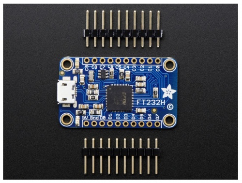
To assemble the FT232H breakout you'll need to solder the included headers to the breakout board. If you haven't soldered before, make sure to first read the guide to excellent soldering and try practicing with some scrap wires and components. Start by trimming the male headers to the length of the pin holes on the breakout board. You should have two rows of male headers with 10 pins each. Then insert the longer pins of the headers into a breadboard so that the pin holes on the FT232H breakout slide perfectly through the header pins sticking out the top of the breadboard. Using a soldering iron and some solder, carefully solder all the pins to the FT232H breakout board. If you aren't clear on the steps above, check out an assembly guide for other breakout boards like the VS1053 audio board. You should follow the same steps to solder the header pins to the FT232H breakout board. Once the headers are soldered to the board, plug in a micro USB cable to the port on the FT232H breakout and then plug the cable into a computer or laptop. You should see a green LED next to the 5V pin on the breakout light up. Congratulations your FT232H board is assembled!
Wiring
Below is a quick description of the pins on the FT232H breakout. You'll learn about these pins in more detail in the Serial UART and MPSSE Setup sections of the guide.
- 5V: This is a 5 volt power source connected directly to the USB bus. Don't pull more than about 400-500mA of current from this pin or else you might damage your computer's USB port!
- GND: This is the ground of the FT232H breakout.
- D0 through D7: These are the ADBUS pins on the FT232H chip and are used for the serial UART and other serial protocols. You can also use some of them as GPIO pins for digital inputs and outputs.
- C0 through C9: These are the ACBUS pins on the FT232H chip and are mainly used as GPIO pins for digital inputs and outputs. Note that pins C8 and C9 are not controlled by software and can only be assigned functionality by changing the EEPROM of the chip. You'll learn more about these two pins in the more info section.
Serial UART
This is great for talking to a serial device like an Arduino from your computer. It's safe to use with both 3.3 volt and 5 volt signals. This means the FT232H breakout can used to safely talk to an Arduino's 5 volt serial ports, and a Raspberry Pi or BeagleBone Black's 3.3 volt serial ports!
When used as a serial UART the FT232H breakout pins have the following serial functions:
- D0: TX or transmit pin. This pin is the serial data output by the FT232H chip and should be connected to the RX or receive pin of a serial device.
- D1: RX or receive pin. This pin is the serial data input for the FT232H chip and should be connected to the TX or transmist pin of a serial device.
- D2: RTS or ready to send pin. This is an optional pin for flow control of serial connections.
- D3: CTS or clear to send pin. Like RTS, this is an optional pin for flow control.
- D4: DTR or data terminal ready pin. Another optional pin for flow control in RS-232 serial connections.
- D5: DSR or data set ready pin. Like DTR, this is another optional pin for flow control in RS-232 serial connections.
- D6: DCD or data carrier detect pin. This is an optional pin that is sometimes used in RS-232 serial communication.
The most important and commonly used serial pins are D0 and D1 for the TX and RX pins. The other pins are only necessary if you're using a device with flow control or specific RS-232 serial needs.
MPSSE Setup
The Multi-Protocol Synchronous Serial Engine, or MPSSE, is the heart of the FT232H chip which allows it to speak many different protocols such as I2C, SPI, and more. When the chip is in MPSSE mode it changes the D0 to D3 pins to have special serial protocol functions:
- D0: Clock signal output. This line can be configured as a clock that runs at speeds between ~450Hz to 30Mhz.
- D1: Serial data output. This is for outputting a serial signal, like the MOSI line in a SPI connection.
- D2: Serial data input. This is for reading a serial signal, like the MISO line in a SPI connection.
- D3: Serial select signal. This is a chip select or chip enable signal to tell a connected device that the FT232H is ready to talk to it.
Windows
To access the MPSSE mode of the FT232H on Windows we need to install special drivers and software. We'll use a tool called Zadig to replace the FTDI driver for the FT232H with a libusb-based driver required by libftdi. Then we'll download a libftdi binary and install it for Python to access. Finally we'll install the Adafruit Python GPIO library. Carefully follow the steps below to setup the software.
➔ First before you get started make sure you have Python installed. You can download the latest Python Version here ➔ Python Download
libusb Driver Install
Download the appropriate Zadig tool for your version of Windows here ➔ Zadig Download. This tool simplifies the installation of a libusb driver for the FT232H device.
1. Now run the Zadig tool executable you just downloaded (there is no installation necessary, the executable is the program).
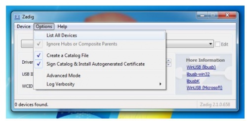
Click the Options menu and select the List All Devices item below:
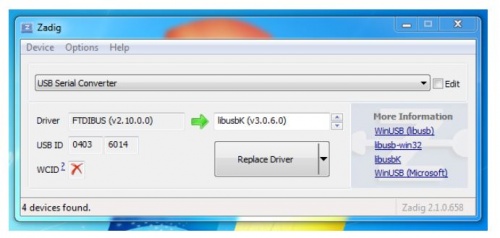
The list box of devices should populate with many devices. Select the USB Serial Converter device shown below.
2. Click the up/down arrows on the driver select box to the right of the green arrow and select the libusbK driver as shown above.
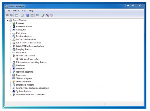
To check that the driver was successfully replaced, open Device Manager from Control Panel or searching in the Start menu. You should see a new
top level node libusbK USB Devices and the USB Serial Converter underneath it as shown below.
If you see the libusbK node and USB serial device, move on to the next step to install libftdi.
libftdi Install
This step will install libftdi's Python library. Carefully follow the steps below to make sure the library is installed. Start by downloading the binary version of the libftdi library by clicking the link below. libftdi Install.This binary is provided by the picusb USB resources project.
We need to copy some files from libftdi into Python's package directory. Open another Explorer window and navigate to the location you installed Python earlier, typically C:\python27. Inside the Python directory navigate to the Lib > site-packages folder. Files you copy into this folder will be available globally as packages that your Python scripts can use.
From the libftdi archive folder, copy all the .DLL files from the bin folder into the Python site-packages folder, specifically:
bin\libftdi1.dllbin\libftdipp1.dllbin\libgcc_s_dw2-1.dllbin\libiconv-2.dllbin\libintl-8.dllbin\libstdc++-6.dllbin\libusb-1.0.dll
Then also copy in the files from the python folder of the libftdi archive into the Python site-packages folder:
python2.7\_ftdi.pydpython2.7\ftdi1.py
➔ That's all you need to do to install libftdi. Let's move on to install the Adafruit Python GPIO library next.
Adafruit Python GPIO Library Install
Finally let's install the Adafruit Python GPIO library which will allow your Python scripts to access the MPSSE functionality of the FT232H breakout. ➔ First download an archive of the library by clicking the button below:
➔ Adafruit Python GPIO Library
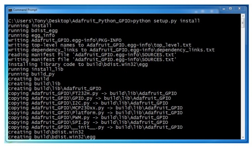
Unzip the contents and then open a command terminal and navigate to the directory where the library was unzipped. Execute the following command to install the library:
python setup.py install
You should see the Python library install itself with text similar to the below:
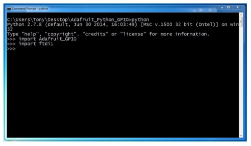
Now let's test if both the libftdi and Adafruit Python GPIO libraries were correctly installed. In the command terminal run Python by executing:
python
Once the Python interpretor has loaded, type the following at the >>> prompt:
import Adafruit_GPIOimport ftdi1
You should see no response from the Python interpretor after entering each command like below:
Once you've confirmed Python can load the libraries, exit the Python interpretor by typing:
quit()
