STM32F407VG CAN
Summary
This document shall provide the reader with a concise overview of how to access, read, and inject messages into an existing CAN system. In this process, an MCP 2515 CAN Controller is utilized in conjunction with an STM32F407G-DISC1 Microcontroller. It is noteworthy that any microcontroller with SPI capabilities can be used for this purpose.
Devices
MCP 2515
The MCP2515 serves as a dedicated Controller Area Network (CAN) controller with key features tailored for efficient CAN bus communication. Employing the CAN 2.0B protocol, this chip is equipped with a Serial Peripheral Interface (SPI) for seamless interaction with a variety of microcontrollers, including the STM32F407G-DISC1 highlighted in this document. With multiple transmit and receive buffers, the MCP2515 facilitates the storage and manipulation of CAN messages, optimizing data flow within the CAN network. Its flexibility extends to bit rate configuration, accommodating diverse network speeds. Furthermore, the MCP2515 incorporates filtering and masking capabilities, allowing selective message reception based on identifiers. This targeted reception, coupled with error detection and handling mechanisms, enhances overall reliability in CAN communication. It is noteworthy that the MCP2515 is designed to work with any microcontroller boasting SPI capabilities, providing versatility in its application across different hardware setups.
STM32F407G-DISC1
The STM32F407G-DISC1 microcontroller board, featured in this guide, is a powerful and versatile device designed to seamlessly interface with the MCP2515 CAN controller for efficient communication on a Controller Area Network (CAN). Equipped with an ARM Cortex-M4 core, the STM32F407G-DISC1 provides robust processing capabilities. Its integrated SPI interface enables seamless communication with the MCP2515, facilitating the exchange of data over the CAN bus. This microcontroller board offers ample resources, including multiple GPIO pins, timers, and communication peripherals. With its compatibility with the SPI protocol, it proves to be an ideal match for the MCP2515 in CAN communication scenarios.
Setup
When programming the STM32 microcontroller, utilizing Visual Studio Code (VS Code) with the STM32 for VS Code extension proves to be a preferable choice over CubeIDE. The rationale behind this preference lies in the more contemporary and streamlined development environment offered by VS Code. Compared to CubeIDE, which some developers might find outdated, sluggish, and less visually appealing, VS Code provides a modern interface that enhances the overall coding experience. The clean and efficient design of VS Code contributes to a faster and more user-friendly development process. The STM32 for VS Code extension streamlines STM32 development by automatically installing essential tools such as OpenOCD, the ARM GCC-arm-none-eabi toolchain, and Make. This eliminates manual setup, ensuring a consistent development experience across Windows, macOS, and Linux. The extension's automated tool installation enhances accessibility and usability for developers, allowing them to concentrate on their projects rather than configuration details.
Manual Project Creation
CubeMX
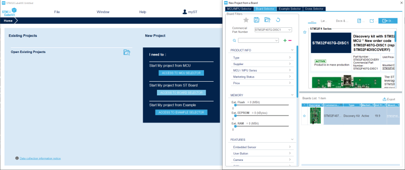
STM32CubeMX simplifies peripheral configuration, generates initialization code, and visualizes pinouts. It eases USB stack integration, a valuable feature for projects involving USB communication. While not mandatory, CubeMX streamlines hardware and middleware setup, saving time and minimizing errors.
Peripheral Activation:
Navigate to the "Connectivity" tab. Activate the SPI peripheral under the specific SPI configuration that corresponds to your project. SPI Baud Rate and Configuration:
Within the selected SPI configuration, locate the baud rate setting. Set the baud rate to a maximum of 10 Mbps, adhering to the MCP2515's limit. Confirm the CPOL (Clock Polarity) and CPHA (Clock Phase) configurations, selecting either CPOL low and CPHA 1 edge or CPOL high and CPHA 2 edges.
Check for a "Data Configuration" tab within the SPI settings. Set the data size to 8 bits with MSB (Most Significant Bit) first.
USB Middleware Integration:
Navigate to the "Connectivity" tab. Access the "USB_OTG_FS" configuration. Set the USB mode specifically to "Device only." USB Middleware Configuration:
Navigate to the "Middleware" tab. Configure the USB middleware settings under "USB_DEVICE." Select the exact class required, such as "Class for FS IP Virtual Port Com." By following these precise steps in your development environment, you can efficiently configure the SPI and USB settings for your STM32 microcontroller project.
Clone Project
If one is using the STM32F407G-Disc1 it is also possible to simply clone this repository: https://github.com/Chronikle135/STM32F407G-DISC1_CAN.git
Wiring
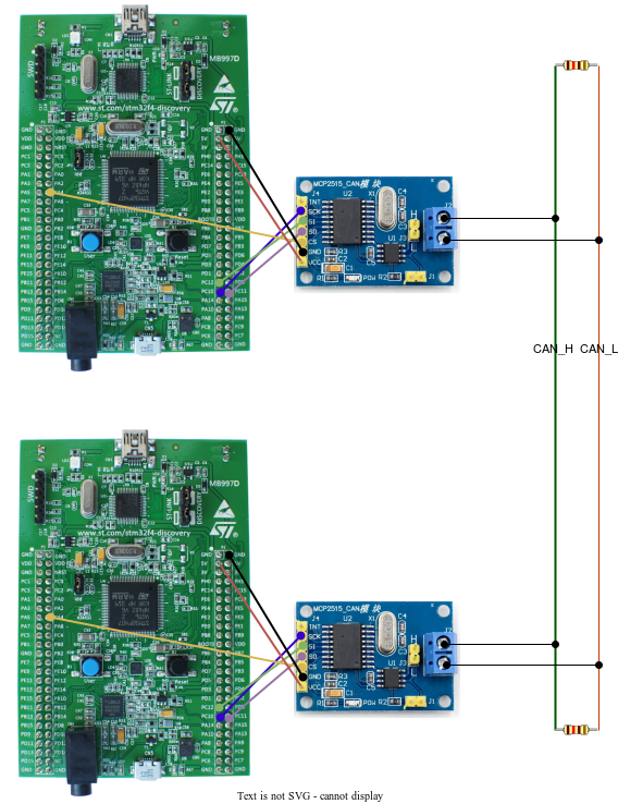
The wiring can be done as shown in figure but is dependent on the configured pins. It is important to connect the MOSI pin on the microcontroller to the SI pin of the CAN controller. Same goes for the MISO and SO pin. The interrupt pin can be neglected.
Code
The basis of this implementation is the standard device driver from Microchip Technology Inc., accessible here. This driver has been further adjusted and made compatible with a standard C library by this GitHub repository. To use this code, it is necessary to initialize the driver with the CANSPI_Initialize() function. Following this, messages can be read using the CANSPI_Receive(&rxMessage) function, which automatically checks the two receiver buffers and retrieves the values from them. If one intends to transmit a message, it can be achieved by utilizing the CANSPI_Transmit(&txMessage) function, which takes a buffer loaded with a pre-assembled message. This message frame should look like this:
typedef union
{
  struct
  {
    uint8_t idType;
    uint32_t id;
    uint8_t dlc;
    uint8_t data0;
    uint8_t data1;
    uint8_t data2;
    uint8_t data3;
    uint8_t data4;
    uint8_t data5;
    uint8_t data6;
    uint8_t data7;
  } frame;
  uint8_t array[14];
} uCAN_MSG
Filter and masks
Out of the box every filter is set to zero, so every message is accepted. Therefore it is possible to sniff the traffic which occurs in the systems. To reduce the load on single CAN nodes one can adjust the filters and masks with the MCP2515_WriteByteSequence() command where the corresponding registers and values that are required should be passed. These can be looked up in this datasheet

