USB Power Delivery Analyzer - Test
Summary
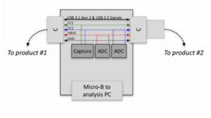
The Total Phase USB Power Delivery Analyzer is a small adapter for recording the Power Delivery protocol traffic on the USB Type-C connector. It connects in-line between two Type-C products, and passively captures all communication between them, on both the CC1 and CC2 signals. While connected, it does not disturb any USB 3.1 Gen 2 or USB 2.0 signals, enabling capture of PD negotiation for power, USB data roles, and DisplayPort, or other Type-C Alternate Modes.
In-Line Capture
- Capture Power Delivery Traffic on CC1 / CC2
- Pass-through all other signals
- Measure VBUS / VCONN
Requirements
- USB Power Delivery Analyzer with a Micro USB to USB type-A cable.
- Data Center Software (Download: here) - to download it from the Totalphase website you will need to create an account. This is not bind with any subscription or cast factor. No installation is needed.
- When using Windows or Linux, you will need appropriate drivers.
- An analysis host computer, which runs the Data Center Software.
- A USB type-C product of which you want to measure the power delivery protocol traffic.
Description
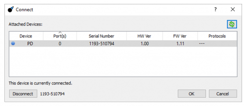
Once the Data Center Software is opened, take the Micro USB to USB type A cable, and plug in the Micro USB connector into the analyzer. The other end (USB type A) has to be plugged in into the analysis PC on which the Data Center Software is running. When this is done, we can connect to the analyzer by clicking on “analyzer” and then “Connect to analyzer” in the Data Center Software:
In the software then start the capture by pressing the “play”-button at the top of the window. A blue light will now appear on the USB Power Delivery Analyzer signifying that the trace is in progress.
The USB Power Delivery Analyzer can then be plugged in into the USB type-C product, which is in this case an iPad. Into the USB type-C port we plug in the charging cable of the iPad. We then insert the connector of the charging cable into the power outlet normally.
As soon as the charging cable was plugged into the analyzer, the analyzer illuminates green or red depending on whether CC1 or CC2 is used to signify the power deliver negotiation is in process.
Hands-On
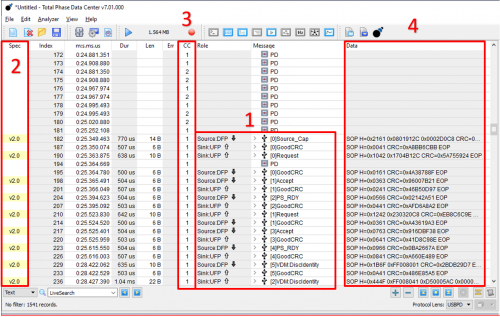
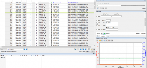
Now we can see the traffic displayed in real time. In the following screenshot we can see,
1. The handshake between the source and target from start to finish
2. The USB Power Delivery specification under the Spec column
3. The capture also includes information to CC1 and CC2 lines as represented by a 1 and 2 under the CC column.
4. Additionally, we can see the PD data captured under the data column.
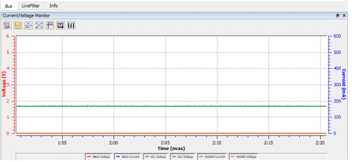
Also included in this trace is an active current and voltage monitor. This graph displays the current and voltage on VBUS and VCONN as well as the voltage of CC1 and CC2 lines as captured by the analyzer.
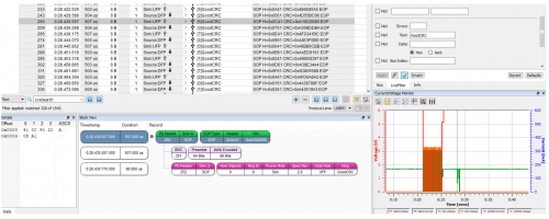
This offers a convenient way to correlate data traffic with events in the power lines. When a data point is selected on the graph, the corresponding data transaction is selected. We can also select the PS Ready data transaction to see the corresponding adjustment in current and voltage on the graph.
If there is a for example a voltage increase, we can also see the handshake for the new voltage again. There should be a sink request for the new voltage and the source accept and PS ready.
The Data Center Software is able to capture any changes to the power reading and all data transactions in real time, allowing developers to see exactly what is happening on the bus.
In the Navigator pane, you are also able to filter for and against specific data or errors for greater insight into the specifics of the USB Power Delivery trace.
As you look at the transaction window and click on a particular transaction, automatically you will see the power window updated. This applies to the Block View and all other widgets are displayed. The Block View shows a just simpler, more colourful view of the information.
This is a quick and easy plug-and-play tool, which makes it an ideal solution for anyone looking for greater insights into the complex nature of USB Power Delivery.

